I haven’t worked often with Arduinos or similar devices (Micro:bits notwithstanding) and the primary reasons are twofold:
- Residual trauma from having written code in C++ years ago
- Working in meatspace is inherently icky to me, as someone who has only dabbled comfortably with software in the past.
Software is often ineffable – particularly when you’re writing in unfamiliar languages and especially when you’re writing code where you have a slippery grasp on the mechanics1. This is exacerbated when the error could be in your software, how you transferred it to the device, in the wiring of the peripherals or in the peripherals themselves.
However, for certain projects, the need to work with physical components cannot be circumvented – and thus, the small necessity of creating an ultra simple USB keyboard, which is actually just a button connected to an Arduino.
We have Arduino UNO R3s coming out the walls here – they seem to have come with various kits over the years and so they’re in plentiful supply.
Fortunately, this guy did it already – seven years ago, no less – and it seems straightforward enough.
I will stress that I am a newcomer to the world of Arduino, so I may have the following things wrong, but as I understand it, the process works like this:
- The UNO has a processing chip that does the execution of a program. It can be programmed to, amongst other things, detect a button push and send a character code (or bunch of ’em) through the USB chip.
- The USB chip exists to provide a serial interface for transferring code to the UNO. Not for being a HID2. But – and props to Arduino for making this so easy – the firmware that runs that USB chip can be replaced, such that it behaves as a USB HID and not for transferring programs.
A Button for Vs
Largely arbitrarily, my connected program requires the user to press “V” in order to trigger a reset. There is no keyboard connected (and I don’t want there to be one). My UNO single button keyboard to the rescue.
Step one is to write the code and transfer it to the UNO. Mine is a little different to other examples I’ve seen:
//A Button for Vs - using external pullup resistor
int ledPin = 8; // My LED is connected to the pin labelled "8"
int state = 0;     // Initialising the state to "not pushed"


uint8_t buf[8] = { 0 }; //A buffer array for our chars

#define PIN_BUTTON 2 //Button is connected to pin 2

void setup()
{
  Serial.begin(115200); //The version of the USB firmware supports a baud of 115200
  pinMode(ledPin, OUTPUT);  // declare LED as output
  pinMode(PIN_BUTTON, INPUT);    // declare pushbutton as input

  delay(200);
}

void loop()
{
  state = digitalRead(PIN_BUTTON);
  if (state == HIGH)
  {         // check if the input is HIGH (button released)
    digitalWrite(ledPin, LOW);  // turn LED OFF
  }
  else
  {
    digitalWrite(ledPin, HIGH);  // turn LED ON
    buf[2] = 25;    // Letter V
    Serial.write(buf, 8); // Send keypress
    releaseKey();
  }
}

void releaseKey()
{
  buf[0] = 0;
  buf[2] = 0;
  Serial.write(buf, 8); // Release key
  delay(500); //This prevents a bunch of presses registering
}
First, there’s the presence of the LED – feel free to omit this. I added it when things weren’t going so well (read on) to provide some indication that the software was actually running.
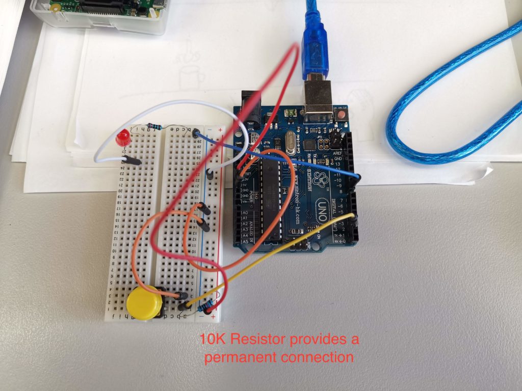
Second, I’ve explicitly mentioned the use of an “external pullup resistor”. I note this, because, as a noobie to the field, I had no idea what the heck this was or even if I needed it. The reference code and circuit diagram ignored it completely (and worked, briefly). Some sites explicitly insist on a resistor being wired in (see below) and others talk about mysterious “internal pullups” and have slightly different code and diagrams without the resistor.
So what gives?
Reasonable explanations abound, if you go looking. In short: it’s not enough to just have a button/switch wired in that can be opened or closed, because meatspace sucks the wibbly wobbly nature of the real world means that all sorts of little voltages can register in that open circuit. This is called a “floating” state, and since it’s undefined, we need to nail it down, and we do that by creating a second part to the button circuit that is permanently connected (and thus permanently either HIGH or LOW, depending on how you connected things). When the button is pressed, it creates a new connection in that circuit, which results in the opposite state. All very predictable and much safer.
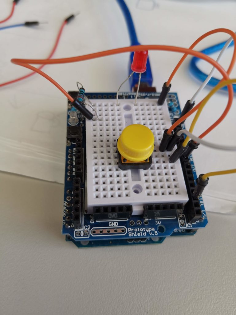
My setup using an external pullup is here:
But there’s a better way to go – the UNO does, in fact, have internal pullups. You can use these instead, by making small changes to the code, and results in cleaner wiring and fewer components.
Code:
int ledPin = 8;
int state = 0;


uint8_t buf[8] = { 0 };

#define PIN_BUTTON 2

void setup()
{
  Serial.begin(115200);
  pinMode(ledPin, OUTPUT);
  pinMode(PIN_BUTTON, INPUT_PULLUP); // It's subtle, but that's the change
  delay(200);
}

void loop()
{
  state = digitalRead(PIN_BUTTON);
  if (state == HIGH)
  {
    digitalWrite(ledPin, LOW);
  }
  else
  {
    digitalWrite(ledPin, HIGH);
    buf[2] = 25;
    Serial.write(buf, 8);
    releaseKey();
  }
}

void releaseKey()
{
  buf[0] = 0;
  buf[2] = 0;
  Serial.write(buf, 8); // Release key
  delay(500);
}
The difference is not super obvious, but it happens where you declare the pin mode for your buttons: pinMode(PIN_BUTTON, INPUT_PULLUP);3
Why did I faff about with resistors so much?
Because I did some silly things first.
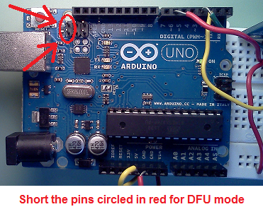
Flashing Firmware – Even when it’s safe, it’s dangerous
Flashing the firmware on the UNO is surprisingly pain-free. You use a screwdriver to short the reset pins on the UNO, you get a program called “dfu-programmer” and point it at the appropriate firmware file and it’s done. More or less.
It was the “more or less” that got me.
You see, the process is a little more involved than that. First, you upload a program like the one above. Then you need to erase the existing firmware to make room for the new one. Then you upload the new one. Then you reset it using dfu-programmer.
sudo dfu-programmer atmega16u2 erase
sudo dfu-programmer atmega16u2 flash Arduino-keyboard_115200.hex
sudo dfu-programmer atmega16u2 reset
That’s three commands which are easy to mix up when you’re in a hurry.
They have to be done in the right order. And if you want to change the program that’s running on your new “keyboard” (for example, to alter the key or add new buttons, or add a longer delay) – you first have to flash it back to the original firmware to let it upload the program, then flash it again to the keyboard firmware to test it.
To make my life “easier”, I wrote two scripts to issue these commands. And because I am super clever, I chained the commands with the logical “and” – && – to ensure that the proceeding commands would only run if the previous command were successful.
My Mac took this to mean “run the commands in any order”4. I spent an hour or so trying to get my formerly working keyboard to do anything, before realising that it was flashing the firmware and then cheerfully erasing the firmware it had just flashed.
Sigh.
The moral here is to run the commands manually, or at the very least read the output which will tell you exactly what it is doing.
Addendum: HID numeric codes for keyboard presses can be found here.