However, that driver clobbers the in-built wireless Xbox 360 controller support – immediately our old Xbox 360 controller stopped working along with the two different 8BitDo Ultimate and Ultimate 2.
I could get the 8BitDo controllers to work by disconnecting their receivers and instead connecting via bluetooth. However, support on bluetooth was iffy and connectivity was a spotty – often requiring a reconnection each time we wanted to use them.
I ended up moving the Xbox controller to bluetooth and removing the Xone driver, keeping the 8BitDo controllers on 2.4GHz.
But then my son “needed” a headset (or, in fact, needed to stop borrowing my wife’s headset).
Options were:
Long USB cable headset (Expensive-ish, inconvenient)
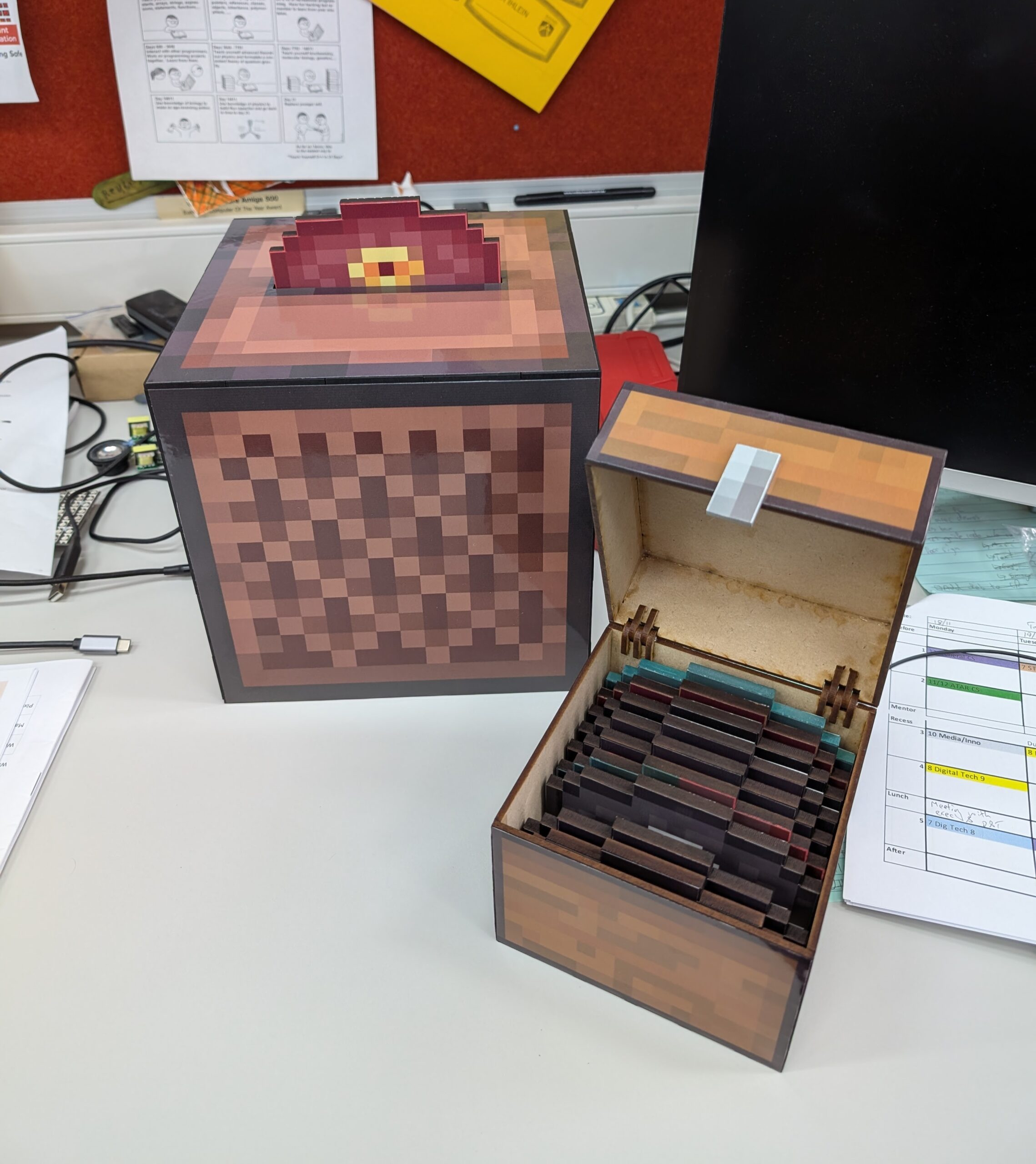
It uses a Raspberry Pi Pico with a limit switch and RFID reader to control an MP3 player – each disc has its own RFID tag.
In addition to the electronic components, the designs are built to work with a laser cutter (MDF – 3mm and 6mm) and vinyl printer/cutter (although if you don’t have access to one of these, a colour laser printer and laminator would do much the same job).
Here’s a demo, in which I managed to pick the two songs with the quietest intros:
Note that there are three copies of each laser cut file – Adobe Illustrator, SVG, and DXF. They should all be the same, but the formats are there for convenience. Each file should have a 10mm reference square that does not need cutting. The file name will indicate the material (all MDF, but you could conceivably use acrylic if you wanted) and the thickness. It’s a bit hodge-podge – sometimes items that are not obviously related are included as I wanted to do cut runs for a particular thickness.
Colours – where there is only one colour, just cut. Where there is more than one colour, magenta indicates cut, black indicates scored (marked, but not cut through). It’s sometimes nice to mark where a piece needs to be glued. I may have been inconsistent with these as I built them up a bit at a time, so use common sense as necessary.
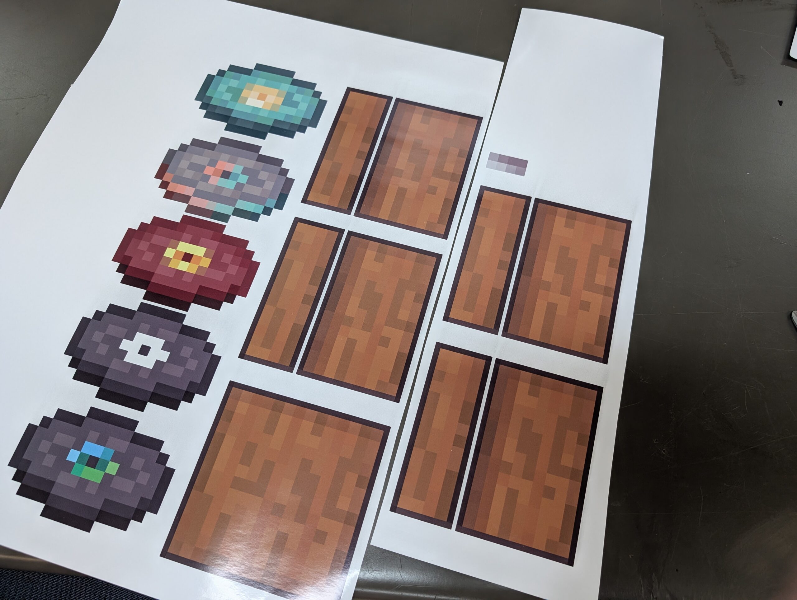
For the printed panels, I’ve included two copies – Adobe Illustrator and PDF for vinyl. The jukebox skin has a file just for printing where the pink CutContour has been removed. At the time I built the machine, our vinyl cutter was unable to cut laminated prints, so none of the other skins have CutContour lines set. If you have access to a vinyl cutter, I’d strongly recommend adding CutContour lines to let the machine do your cutting (especially for the discs). Note that as all my printing was on a vinyl cutter (which is large format), the sizes in the PDFs for printing may not be great for regular A4/A3 printers. Some editing may be necessary. Either way, I’d strongly recommend laminating these panels as wear is likely.
Assembly
Most of the laser cut panels will slot only where they are supposed to go – one or two items (such as the RFID support above) need to be positioned manually and glued. For MDF, always use PVA glue 6. Hot glue is an awful adhesive and super glue is probably overkill, but you do you.
I haven’t determined an effective way to mount the Pico – it probably deserves a little MDF cage or something, but it wasn’t on my list of priorities, so there is some movement inside the box. Feel free to design something up and send me the changes!
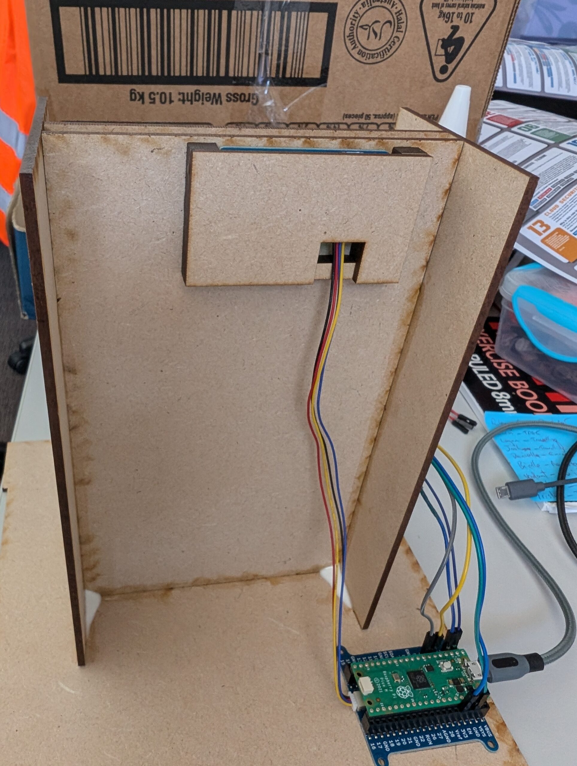
Wiring the Pi to the MP3 player:
Pin 4 on the Pi is wired to the RX on the player; pin 5 is wired to the TX. In the code, you’ll note the pin variables are labeled with 4 and TX and 5 as RX – in other words, the Pi listens on the pin that the player talks on and speaks on the pin the player listens to.
Power the player using the 5V VBUS pin, as indicated in this post. Although the player can use 3V, it appears the Pico is often unable to provide consistent power for it through this pin.
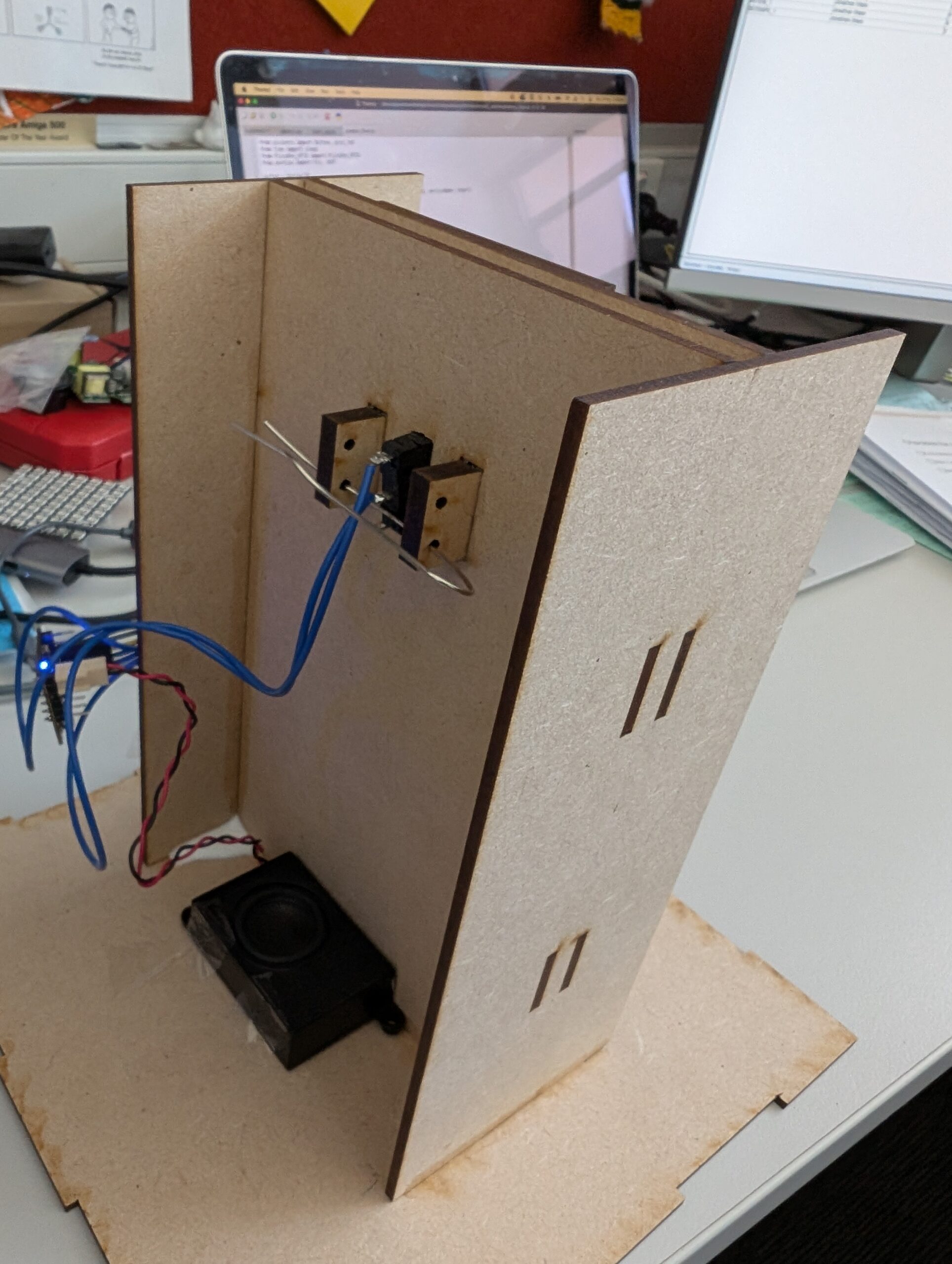
Weirdly, the switch was the component that gave me the most grief. It was a pain to cut and resize the hole for it, as it needed to be snug in order to give enough resistance when the discs were inserted. I ended up the little supports in the image – but managed to cut them 3mm too wide as accounting for material thickness appears not to be my strong suit. I believe I have resolved this in the design, though I just made do using ones pictured in my final build. The idea is that the holes in the supports line up with the mounting holes in the switch, allowing for pins to be inserted to hold the switch in place.
What actually happened, is I twisted a paper clip into a shape that could hold the switch, found that it had too much give, super glued the switch to the MDF in frustration and ended up with vapour from the super glue coating the contacts inside the switch, making it useless.
Oops. I had to pry it out and replace it with another, smaller switch that I had on hand with two paper clips bent to size – the final design is decidedly jury-rigged, but it has held well for dozens of plays, so it’ll do.
I’d recommend you customise the design to match your limit switch dimensions and mount using pins/straightened clips per my original plan, but honestly, this seems fine.
I’ve wired my switch to pin 1 on the Pi and my code reflects that. Change it up if need be.
Vinyls/Skins
One lesson I’ve learned from previous projects is to use paint pens to go around the edges of the MDF before applying vinyls.
Posca pens are not cheap, but make the task particularly quick and easy. If you’d prefer to go the traditional route, that should be fine too – I will, in future, make my skins a little bigger – less wiggle room when applying, but less of the base material will show, which I think is worth it. You can scale your prints to something like 105% if you want to cover more of the MDF.
RFID Tags
Any standard RFID tags should work – Core Electronics does stock ’em, but not in the quantities we need – making them not a cost effective way to buy tags. The Amazon store linked to above sells them in various sets and they worked great, with the exception of exactly one tag that works fine with my phone but mysteriously won’t trigger the PiicoDev RFID reader at all. As I bought a set of 12 and had 10 discs, it wasn’t a big deal – but probably worth checking each of yours before applying the tags 7. Vinyls go over the RFID tag, leaving a pleasing bump where the thickness of the sticker shows slightly. As RFID tags trigger from a few centimetres away from the reader, the discs can be inserted in any orientation and still work with the jukebox.
It can be used as-is, but for two rather big caveats:
Each disc needs to be assigned to its RFID
The MP3 player is bonkers and you can’t predict what track number is what
Now, you may be thinking, “Jonathan, why not just play the tracks by name?”
That would be great, but the player won’t allow me to do that when I’m controlling it via serial – the DFRobot Wiki does provide some documentation and a library for Arduino, but I’ve found communication via my home-brewed code on serial to be… inconsistently implemented.
The obvious solution would be to use an Arduino instead of a Pico – the library seems to be fairly robust and fully functioning from the odd times I’ve played with it – but I don’t want to use an Arduino, and I’d prefer to work with the PiicoDev RFID reader 9.
So… what doesn’t work/is quirky when driving this MP3 thing via serial?
First: It’s supposed to have a call/response implemented, but I can’t ever read the responses from the player – though you absolutely do need to leave spaces in your code to receive the reply, including a short wait time:
mp3_player.readline()
sleep(0.5)
Not leaving these in will result in complete non-cooperation from the player. It’s like having a weird one sided conversation, where the other person doesn’t ever say anything but will get up and leave if you don’t provide a pause for them to talk. I could well be doing something wrong here, but hey, this gets us what we want, so for now it’ll serve. Oh, and you’d better make sure you include the carriage return and line feed characters at the end of every serial write (“\r\n”) or the thing will refuse to communicate as well. It’s all very “simon says”.
Second: You’re supposed to be able to call tracks by name, but I got zero traction trying to use those commands. Instead, I can call the tracks by “number”, like so:
mp3_player.write("AT+PLAYNUM=12\r\n")
…except… there seems to be no sensible order to which track is which number, including the occasional double up (eg, track 3 and track 4 both being the same file). This is exacerbated if you’ve added your tracks using a Mac OS system – Mac likes to leave its little trail of nonsense directories and files for the convenience of Finder, but the player gets really confused by these ghost files. Removing them via a Windows or Linux system makes the whole process much more straightforward, but there’s still no getting around the fact that you will need to write code to play each track number in turn and then record which is which. Just make sure all your tracks are on there before you run the code, as new tracks can interfere with the order.
You might think that sticking a number in front of the file name will make the process more predictable – it seems to have some effect, but isn’t predictable enough to ensure that track 07 will actually be track 7.
Third: The “prompt” – when the device is first powered on, it’ll loudly announce its mode. This is undesirable. It’s easy enough to run a line of code once to switch this off:
mp3_player.write("AT+PROMPT=OFF\r\n")
Finally: The stop command doesn’t. There are various references to “pause” in the documentation, and I believe it works using the Arduino library etc etc, but I just simply could not get it to work via plain serial in Python. The solution? Well, the player does function correctly in its “play track once and then stop” mode. I think you see where this is going.
I have a short track which is silence (not too short – I received some unpredictable behaviour/pops when using a track <=1s) and this is played when I want a track to stop (ie, the disc is removed).
It does the job.
You can use the AT commands to set the volume, so there’s lots of scope for additional controls/wifi controls if you desire:
mp3_player.write("AT+VOL=20\r\n")
The docs indicate the volume can be set from 0 (mute) to 30 (max). 20 (two thirds) works for me, YMMV.
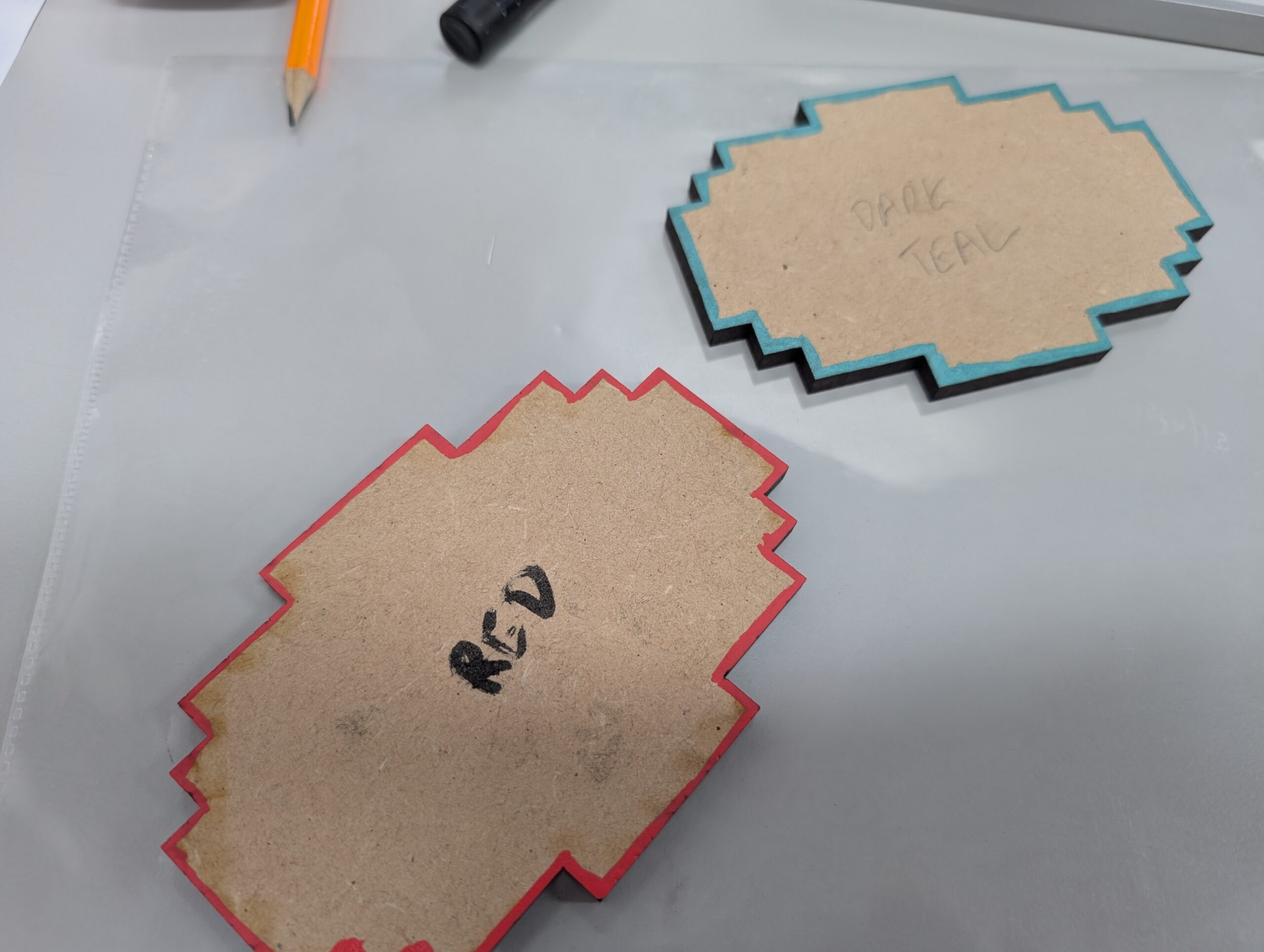
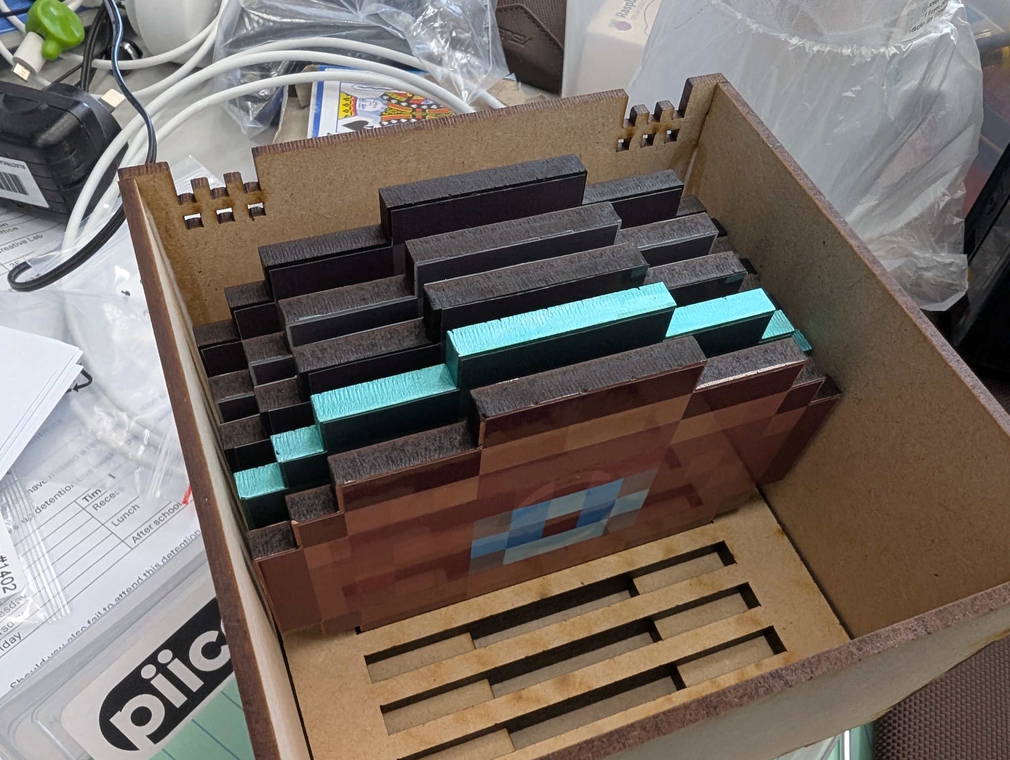
Disc Fit
The design allows for the shape and size of each disc to slot exactly into place, both in the storage chest and the player itself. If you don’t line up/adjust the disc exactly right, it won’t sit level which is slightly annoying.
I’m calling this design a “feature” to encourage better fine motion – it’s occupational therapy!
In reality, it’s a design flaw that needs to be fixed. An improvement would be to shave the sharp corners off the disc support and make them diagonal – this would improve the experience when inserting the disc into the player.
As the chest supports are perpendicular (horizontal cuts) this is not an option. For future designs, I would make the upper support panel a couple of mm longer in order to be more forgiving and make the lower support panel a single cut rectangle, allowing it to be sanded down on the top edges.
An alternative for the lower panel would be providing each individual disc with its own support – this way the design could be laser cut at an angle, eliminating the need for sanding, but introducing a fiddly task for positioning the supports (cut slots in the bottom of the box? Add a third panel with slots?).
No obviously perfect solution exists, but I’ll update with the results of attempts to improve this feature.
Music files
You can acquire the actual music files in any number of ways, but I downloaded mine from this tool here.
The tracks I selected were the ones I found most “listenable”, but there are 19 available at the time of writing.
Other future improvements
For a redo of this project – provided I can get the vinyl cutter to actually cut laminated print jobs – I’ll look at addressing the size issue. Within the game itself, the jukebox and chest blocks are the same size; it doesn’t particularly bother me that the chest is smaller, but it may be worth either sizing the chest up (and storing more discs) or sizing the jukebox down (and potentially shifting to 3mm thick discs).
In either case, non-trivial modifications will be required to the schematics.
At the completion of year 11 exams, students at my school are expected to return for 4 weeks to “begin year 12”.
Rather than set a bunch of individual assessments, or run a formal test only for students to disappear on 8 weeks holidays, I prefer to work on a collaborative multiplayer game – a different one each year – which is closer in development approach to a game jam than a traditional cycle or scrum.
Prototype: Chestral
The first year we did this, we created Chestral – a simple game which set the structure for the two subsequent projects.
The goal was to have a “main screen” server which presented the graphics, progress etc for all players to look at, while the clients connecting to the server would be coded by individual students and would effectively be minigames.
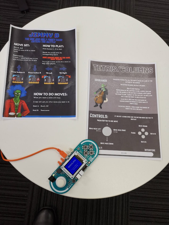
Alysha’s and Kelvin’s client instructions. Creating documentation was a big part of the project.
The implementation is very similar to the Jackbox Games model – everyone looks a one big screen while each having their own little ones. In Chestral’s case, the actual game itself was designed to be like an MMO raid boss fight.
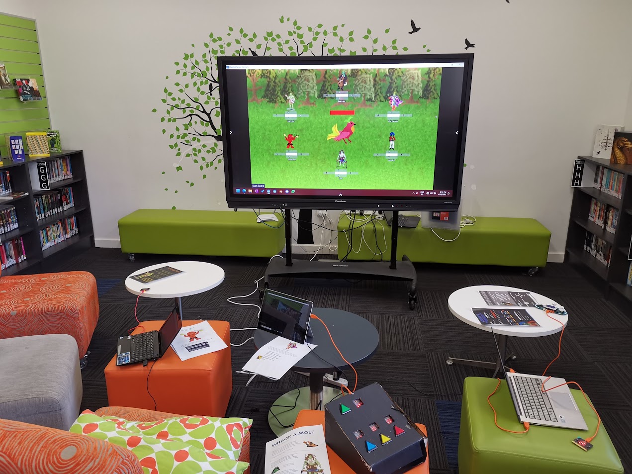
The final setup on Showcase day. Each client had its own specific hardware requirements, which was a nightmare.
Chestral was overly simplistic in its rules for clients – most players would just focus on their client’s minigame and let the “raid leader” – the Maestro – handle the encounter.
It was still fun, and there was an enormous depth and variety of learning (client/server models, APIs – even getting the hardware to run the clients on the day was a huge exercise) and excellent engagement, as all the 11s turned up on our school’s showcase day to set up and exhibit the game, despite it being their first day of holidays.
Terminal:Exploit
My next year 11 class was working in the new Computer Science syllabus – which is far more demanding (particularly with regards to programming) and this meant a higher standard of complexity could be expected from the clients they produced.
Terminal:Exploit was conceived as a game structured around the cyber security and network protocol concepts covered in the course. In contrast to the cooperative nature of Chestral, Terminal:Exploit pits two teams of four against one another.
We kept the same overall client/server structure (one big screen, each client has small screens) but took the lessons of Chestral’s implementation (don’t design your clients to run only on the developer’s hardware!) and specifically developed the clients to
All have identical hardware/library requirements
Be purely text based (hence, terminal)
Be designed for specific, available hardware (SOE laptops provided by the school)
Some of the more ambitious students pushed for clients which were Godot implementations, rather than terminals, but these were not able to be integrated in time.
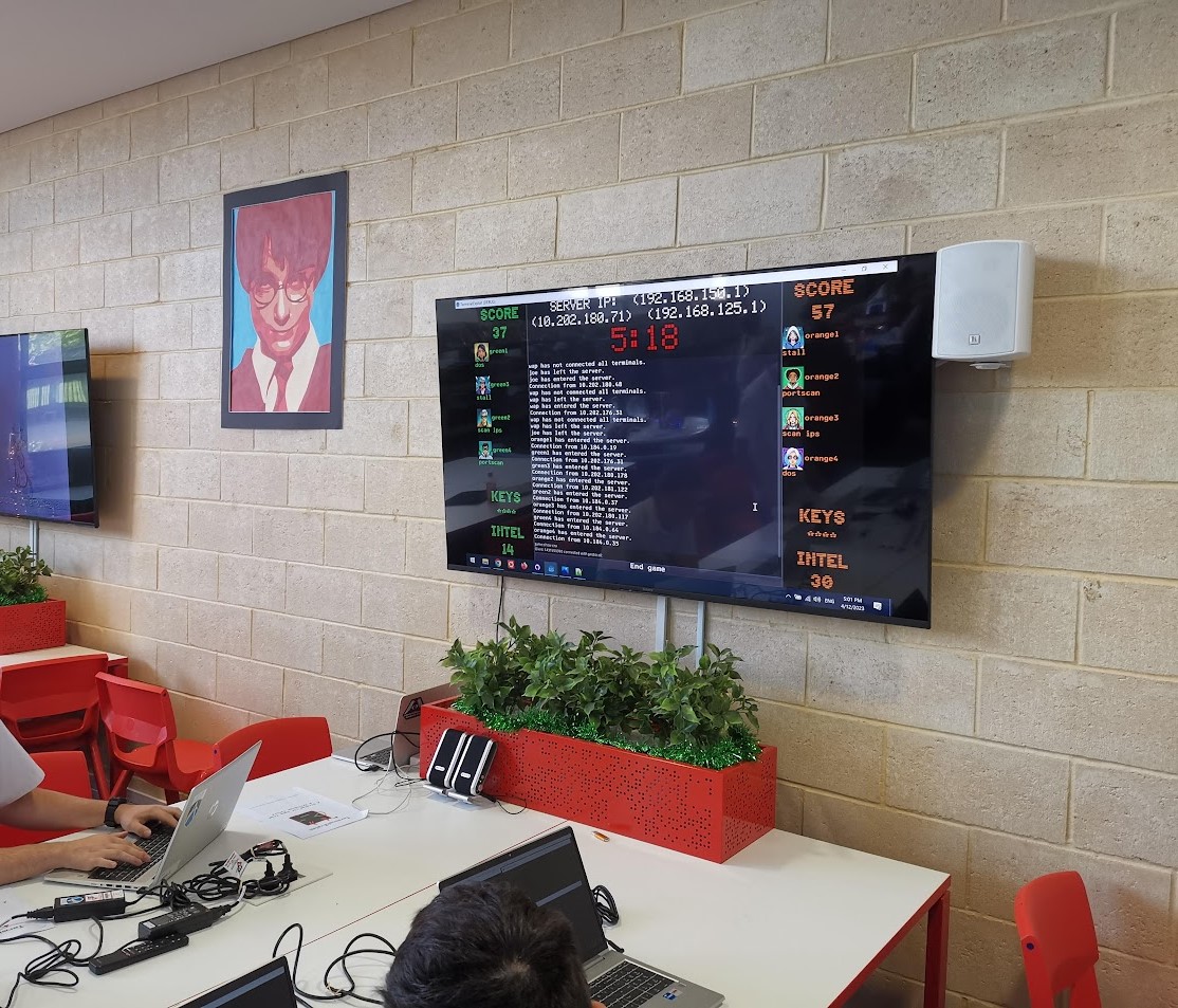
T:E is a more exciting and more complete game experience when compared to Chestral; the learning curve is steep and the concept is so abstract as to frighten off prospective players, but once you’ve played a round or two, you get the hang of it and it becomes a very compelling team PvP experience.
The game objective is simple enough – either steal all your opponents’ keywords before the game timer expires or have more points than the opposing them when the timer does expire. Executing commands in one of the terminals to “connect” to your opponents allows you to discover and claim their keywords.
A typical client device will look like this:
There are actually three terminals on the screen for each client!
It would be technically quite possible to combine the functionality of all three terminals into one – but this would require a more aggressive use of threading, which I wanted to avoid, and make the separation of tasks more complex (a single student worked on the command terminal in the bottom right, two students worked on the status terminal in the left hand side and each game terminal was different depending on the client mode).
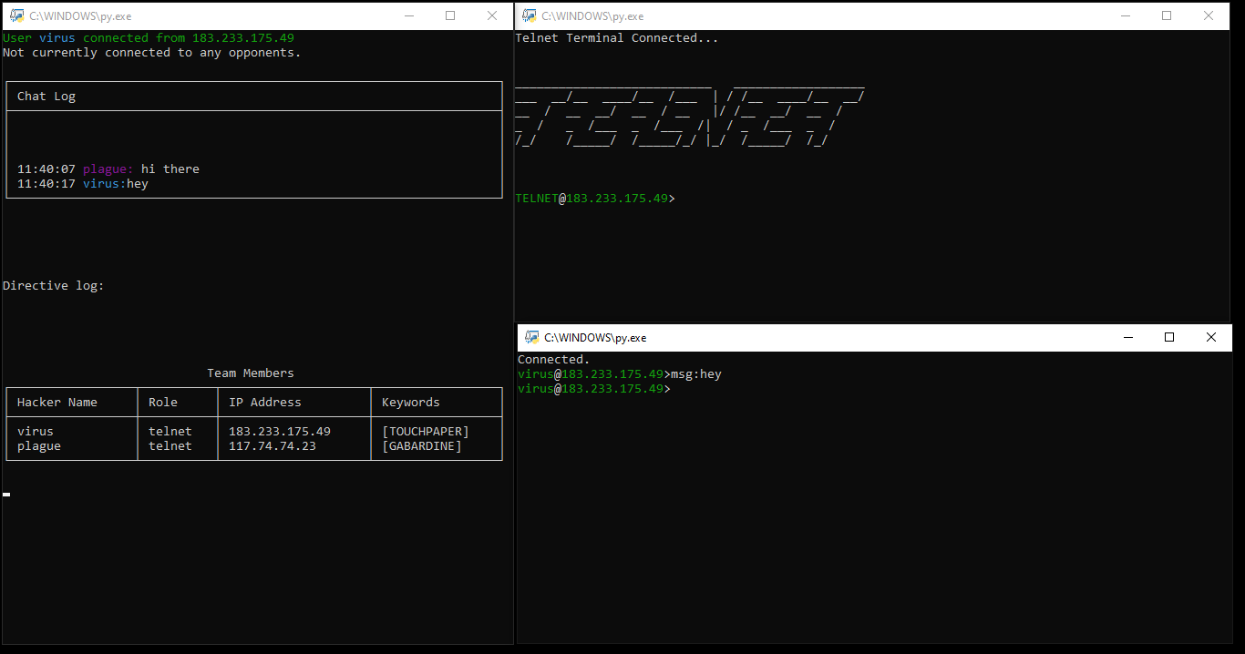
Clockwise from the left side terminal:
Status terminal. Non-interactive, this terminal provides a 5 line chatlog for your team, current directives (instructions for use with the game terminal) a table of team members and keywords, and, once the game starts, a table of opponent data as it is discovered by your team.
Game terminal – in this case, telnet. In theory, each game terminal was intended to be a new protocol – the player must manage their “server” to earn points and intel to be used in the wider game. In practice, we only managed to get two game modes running – telnet and SMTP. Partially/mostly complete were FTP and SSH terminals, along with more free form/less terminal-like modes UDP/TCP (simulating packet processing, similar to a firewall) and YTOS (simulating scheduling on an operating system).
Command terminal. The command terminal is a general purpose thin client – it allows players to communicate with their team as well as move keywords around and use abilities. In addition, the command terminal is the terminal from which a player can “connect” to an opponent’s game terminal.
Much work was done to ensure these client terminals would run on the provided systems and automatically size to fill the screen.
The majority of the processing was performed server side – this was a double edged sword. It allowed for fairly rapid development of the status and command terminals, but necessitated that the game terminals have their logic split between the client and server. Students either struggled to create code for the server to handle their game terminal or simply left it to me entirely. This was definitely a factor in the number of incomplete game terminals; on the other hand, the “connections” made from the command terminals simply could not have actually gone through to game terminals without making client development significantly more complex. I’m chalking it up as a wash; the concept behind T:E didn’t lend itself well to this specific aspect of student development, and no “best” approach exists.
Fans of Friends at the Table might notice the keywords are a little familiar – they are taken directly from the finale of Partizan (and its soundtrack). In fact, on showcase day, we used the Partizan soundtrack (from the incomparable Jack de Quidt) as music for the game. Slow, menacing, disorienting – perfect.
Of Aesthetics
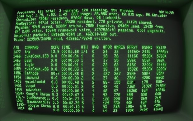
The sort of terminal look I was channeling – image taken from this post
My original vision for T:E was to recreate the vibe of 70s and 80s terminals – often two-tone black background affairs with either green or orange text. The conceit is that the game is set in a dystopian future, advanced hardware and software is either lost or inscrutable – leaving rival gangs to manually manage their own servers in a deiselpunk wild west Internet.
I’m happy with the overall impression the game makes – it looks a lot less accessible than it is – which might seem like a totally backwards intention, but for me, that is the hacking scene of the 70s and 80s.
In order to play, you need to refer to a printed manual, a feature I find to be as delicious as it is absurd in the 2020s.
Merits as a Game
Is this a good game?
I think so – it’s generations ahead of Chestral in complexity and user satisfaction. Certainly, the next year’s group of students, once they got the hang of the interface, were excited to play it more than a few times.
That said, its incompleteness is its downfall – given the limited number of game terminals and the lack of progression for each one (we had envisioned a skill tree of sorts to allow each player to fill different roles more effectively), the replayability is limited. I anticipate after around a half dozen games, the shine will have worn off and players won’t want to come back.
Merits as a Learning Tool
Does this game, in and of itself, have educational value?
I think so – I find that students (and adults) generally have a fear of the terminal, often not having any idea of how to use a command line interface at all. T:E creates a motivation to build familiarity with the interface and there’s some value there.
Do players learn much about the protocols? Probably not – many liberties were taken when conceiving of the game loops for each terminal and so those skills don’t particularly translate over. That said, the SMTP game requires players to literally type SMTP protocol commands to send an email, so I guess that’s something? They learn how awful SMTP is?
There’s also some value in the basic concept of using the command terminal to connect to another player’s IP address and port (both completely fake on the backend – each terminal connects only to the server) so this might assist in understanding the concept of devices having IP addresses as well as ports for individual services.
Beyond that, communication and collaboration need to be used to have a successful team – so don’t rule out those “soft skills” as benefits.
Merits as a Project
This project pushed my students more than Chestral, so in that sense it was successful.
The abstract nature of the concept was a huge barrier to students starting – they needed to see the concept in action to grasp what was required of them, which reduced the amount of productive working time.
Students all used git repositories to manage and share code, which is an invaluable introduction to the concept of version control systems.
We pushed the idea of developing for a specific standard operating environment during this project and students were responsible for deploying and testing to this environment – which I believe to be worthwhile as it is an experience missing from a typical high school project.
And, as with Chestral, almost all students turned up to set up and demonstrate their project on what would otherwise have been their first day of holidays, so I think that speaks volumes to engagement and motivation for students.
Not an unmitigated success, but certainly a project of which I’m very proud.
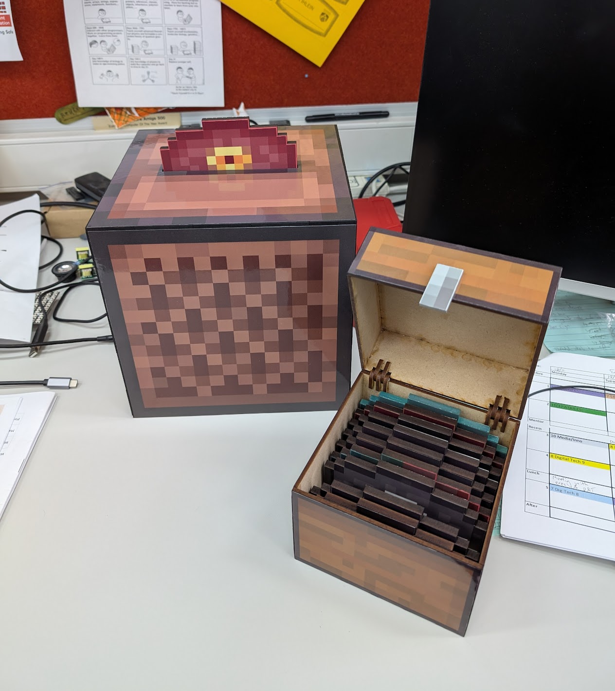
And I’m reasonably happy with it – it’s a fairly simple construction, laser cut boxes + vinyl cut stickers.
The internals consist of a Raspberry Pi Pico with a limit switch and RFID reader. Each disc has a small adhesive RFID tag. When the disc is inserted, the limit switch closes and triggers the RFID reader to check the ID of the tag which can be used to play the appropriate track.
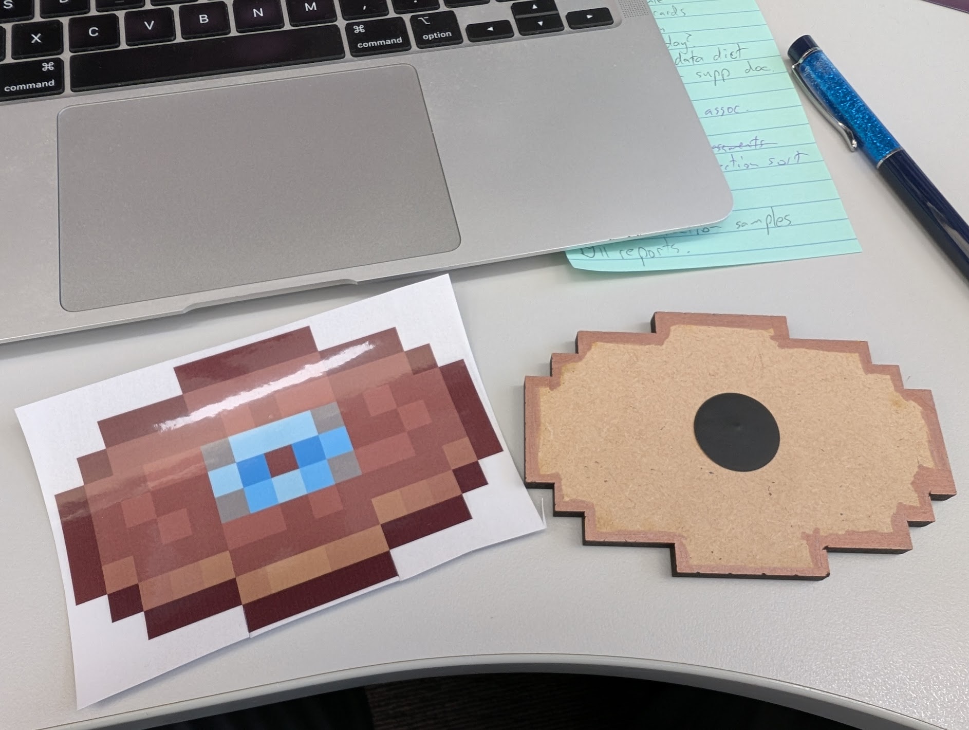
Disc with RFID tag
The tracks are stored on, and played by, this MP3 player – which I’ve used before and overcome its myriad quirks (more on that in another post).
The MP3 device is powered by a 3V pin on the Pico. It worked great while building – discs were tested extensively during construction. I even found a tag that seems compliant with specs but would not register with the Pico’s RFID reader for some reason and had to be replaced.
I discovered an issue upon connecting the device into an external power source, rather than my laptop – around 30s into a song, the unit would just cut out. Suspecting power, I changed the cables and chargers to no avail. Connecting the Pico back into my laptop resolved the issue.
Curious.
The Pico has 3 different options for providing power:
3v Pin for, well, 3 volts
VSYS for 5 volts – my understanding is that this is the main supply to the Pi and may actually vary below 5 volts
VBUS for… 5 volts again. This is straight from the external power though.
I was powering my MP3 player via 3V, and while the current required by the player should not have been more than the Pi can provide, I suspect it was either fluctuating below 3V or tripping something in the Pico itself. Connecting the player directly to VBUS seems to have resolved the issue (thankfully the player can handle anything from 3-5V).
Just something to remember next time weird things start happening when connecting to a new power source.
I’ve recently (~6 weeks ago) replaced the very janky MPD server setup in my kitchen with a smaller Raspberry Pi 3B + DAC hat.
When I’ve attempted to run this setup in the past, it’s worked fine for maybe a week and then I’ve had network response issues – the CPU seems okay, but network connectivity is so bad, I can’t even SSH or send through an MPC stop command.
I originally figured that the issue here was weak WiFi on the Pi + weak WiFi access point and left it at that – since I seemed not to get the issue when I moved the pi into my office and connected via Ethernet.
However, I have a shiny new WiFi AP now, which has much better range and reliability, so I figured I’d give the Pi a go again – no fan, lower power usage, quiet.
Worked great! Until yesterday.
Yesterday we had a power outage. I still haven’t configured my media devices to retry NAS connections after power outages, so they often need to be re-rebooted when this happens so that they can access media libraries. This was the case with the Pi.
When it came back up, MPD was accessible but… slow again. And then songs would stutter out or controls would be unresponsive. SSH struggled to connect.
It was the old set of problems all over again.
But why?
I tried:
1) Completely unplugging the Pi and its PSU and leaving them before plugging back in – capacitors are sinister majicks, so maybe this was related to the power outage? 2) Updating the system 3) Disabling the GUI on startup (may have already been that way) 4) Checking for undervoltage messages in dmesg (none) 5) Checking wifi connectivity (iwconfig wlan0 – 64/70, no signal issues) 6) Swearing
None of these worked. Time for bed.
Upon investigating this morning, I had two “finds”, both from the mpd.log file: *Lots of “alsa_output: Decoder is too slow; playing silence to avoid xrun” *Lots of “zeroconf: No global port, disabling zeroconf”
Both these messages appeared AFTER the day of the outage but not before (except one zeroconf a few days earlier – but not 5 within a few minutes like I was receiving after)
I found a few threads similar to this one which suggested the zeroconf issue was systemd related – the “fix” suggested there did not help me.
(Also: I’d been using systemd since day one and not had this issue)
Searches relating to the “decoder too slow” message yielded little; my CPU was never the issue and my wifi connection was solid.
I tried changing the MPD config to include these settings for my output, per some suggestions:
buffer_time “200000” period_time “5084”
This did nothing.
The zeroconf issue puzzled me; I don’t need or use it, but had never had these errors before. Couldn’t I just disable it? At least that’s one fewer error to confound me.
In the mpd.conf file, you can find a line enabling/disabling zeroconf: zeroconf_enabled “no”
This… fixed it?
It doesn’t make a lot of sense.
My current hypothesis is that actually there is some deeper problem causing this issue and zeroconf failing was exacerbating it – my MPD client is still a bit sluggish, but not unresponsive like before.
I have no idea why this happened or if it is related to the power outage or if something updated and broke things. I’ll leave it for now and see how it goes.
Our house received an upgrade to full fibre optic last year, and with the increase in available home bandwidth came the opportunity to retire our old NetComm router/modem/WiFi unit, which had been, if we’re generous, “adequate”.
Or, in fact, inadequate in a number of ways – its WiFi range was actually abysmal, something I only found out when I migrated to a dedicated WiFi unit and discovered that a single device can actually cover our entire property.
Also, it “supported” IPv6, in the sense that it could, technically, have an IPv6 address for a brief period of time, before just quietly giving up on routing IPv6 traffic until you either reboot or get exasperated and switch off IPv6 support.
So in the spirit of questionable decisions, and egged on by friends who are far more skilled and experienced in this sort of thing, I purchased a cheap all-in-one fanless PC with four 2.5Gb ethernet ports.
In this house, we enumerate from zero
For the curious, it runs at around 55 degrees in the Australian summer, 65 if I make the CPU think hard. Certainly an improvement over the poor old Mac mini I have running as an MPD server in our kitchen, which routinely idles at 80 degrees.
Because I can’t ever be content to do things the easy way, I put Proxmox on it first, with the intention of running OPNsense as a VM, alongside a PiHole instance.
My initial set up experience was tainted by an inability to get OPNsense to register a connection via the WAN port, which resulted in around 45 minutes of frustration before realising that my ISP requires me to manually “kick” connections between router changes. As a result of this faffing about, I now at least have a document detailing exactly what each of the physical ethernet ports are called in Proxmox and what their MAC addresses are – probably something I should have sorted out before doing anything else anyway.
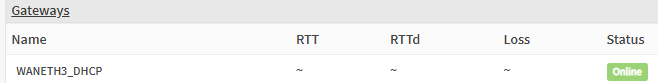
Once the router had a connection, everything ran great. For thirty minutes. After which, the router simply couldn’t talk to the gateway any more. No Internet connection.
In OPNsense’s dashboard, it indicated that EVERYTHING IS FINE. Which, you know, not true.
This is a lie.
A reboot results in the same behaviour – everything is fine for around half an hour, then no WAN connectivity. Renewing the WAN connection fixes things… indefinitely. Until another reboot.
Thus began The Troubleshooting.
Various settings and configs were checked. IPv6 disabled (just in case), hardware VLAN filtering disabled etc etc
Same behaviour.
Install a completely fresh OPNSense VM – exact. same. behaviour.
And the whole time – once I renew the WAN connection, it fixes itself for as long as it remains up. The command I ended up running in the shell:
configctl interface reconfigure wan
Magically fixed it… but only if it had already broken. That is, I couldn’t just run a renew at the end of the boot sequence and call it a day – I had to wait until the WAN connection failed before I could renew it – and that just didn’t fly (not that appending some magic words to a startup script would have made me happy).
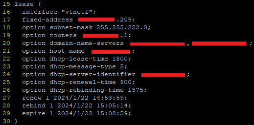
I ended up digging through the DHCP client leases file in /var/db (in my case dhclient.leases.vtnet1) and noticing some strange overlaps in the renewal/rebind/expiry etc times.
These leases files look like this:
Turns out, this a log, rather than a config – FreeBSD is writing the dates and times there as a record, not an instruction. But this was the clue to help figure it out – when router first booted, the lease file was written to but the time for renewal and expiry passed without the router even trying to renew the connection.
Once I reran the renewal command manually, it worked fine, but crucially, it was writing dates and times that were wildly different to the initial time on bootup.
Anyway, as with all things, it was DNS.
A haiku
Well, sort of.
When I set up the initial Proxmox install, I somehow (?) managed to set its DNS server to be 127.0.0.1. Surely that can’t have been the default?
Anyway, that meant that while it could do all the work of creating VMs just fine, it couldn’t, among other things, talk to NTP servers to figure out the time.
But it did know it was in the UTC+8 timezone. And it did assume that the hardware clock was in UTC time. Which it wasn’t. It was set to local time. So my VM host believed it was 8 hours ahead of when it actually was.
When my router booted up, it was given this time and it then obtained a lease and made a note to renew that lease in 15 minutes. 30 minutes, tops.
But it then used an actual DNS server to do an NTP lookup for the correct time – at which point it said to itself, “hoo boy, I am 8 hours ahead of where I should be! Lemme just fix that right up.” But its lease now thinks the expiry is not for another 8 hours – hence failing to renew and not having any WAN connectivity.
To add to the confusion with all this – FreeBSD in all its wisdom writes dates and times to the lease file in universal coordinated time – not local time – without any indication that this is what it is doing. So when the router first obtained that lease and wrote the wrong time to the log, it looked to me like the correct time, but when I renewed the lease manually, it had corrected its own time and was now logging, what appeared to me to be 8 hours in the past.
Obviously, I think everything should always just be in UTC and that there are no problems or issues that would or could be caused by adopting a world free of timezones, but, please, indicate that somewhere, hey?
Anyway, OPNSense seems fine and good. I’ve managed to do some port forwarding and set up queues to minimise bufferbloat, so all is right with the world.
Perhaps you, like me, use an MPD server to manage and play a largish music collection. Perhaps, you, like me, are finding the odd weird thing happening in your client where multiple albums appear for the same set of tracks, or tracks are split between two different, yet somehow identical albums.
Probably not though. However, this post exists to provide me with a reminder of the techniques used to resolve those issues.
Before we begin, my primary client for this library is MALP on Android – it’s actually very good, but gets grumpy if your MPD is old (FWIW mine is 0.22 – I went to the trouble of compiling by hand) and is very strict about some tags (which is a Good Thing, but can be fiddly)
Step One – Basic Tag Hygiene
Make sure the tracks for your album all have ID3v2 tags (remove all the v1 tags – don’t need ’em) and that the track numbers, total tracks, artist, albumartist and album tags are all correctly set. Any variations here can cause issues where a track magically belongs to a different album with the same name, or lives on two different albums somehow
Step Two – Check for MusicBrainz Tags
The MusicBrainz project and its tagger – Picard – are wonderful. However, music releases are squirrely and it can be hard to pin down exactly where your tracks fit in the listed releases.
In an ideal world, you can just add the appropriate release on MusicBrainz and Picard will simply tag all your tracks correctly – done and dusted.
imdoingmypart.gif etc etc
But not all tracks belong on MusicBrainz. And not all albums exactly match the releases. If you’re me10, you have music that just isn’t on MB at all and never will be.
The issue comes from when some tracks in an album have been tagged previously by Picard, but others have not – because Picard leaves behind super secret custom tags to help organise music. Which is great, except that MPD and MALP can read these custom tags and if not all the tracks in an album having matching ones, weirdness ensues.
So I downloaded this thing, which does a very specific job, but I used it solely to view “extended tags” and delete all the MB related stuff for albums with a mixed tagging history.
Step Three – Disc numbers?
If some of your album’s tracks have been tagged “disc 1/1” or similar and some have nothing in that tag – these tracks will still appear on one album, but the order may be all wrong. Just make your tags consistent – either all disc 1/1 or no data in those tags.
Empty tags for this can be intepreted as “disc 0”, causing those tracks to be erroneously listed prior to others.
That’s all I have so far, I’ll update with screenshot examples later.
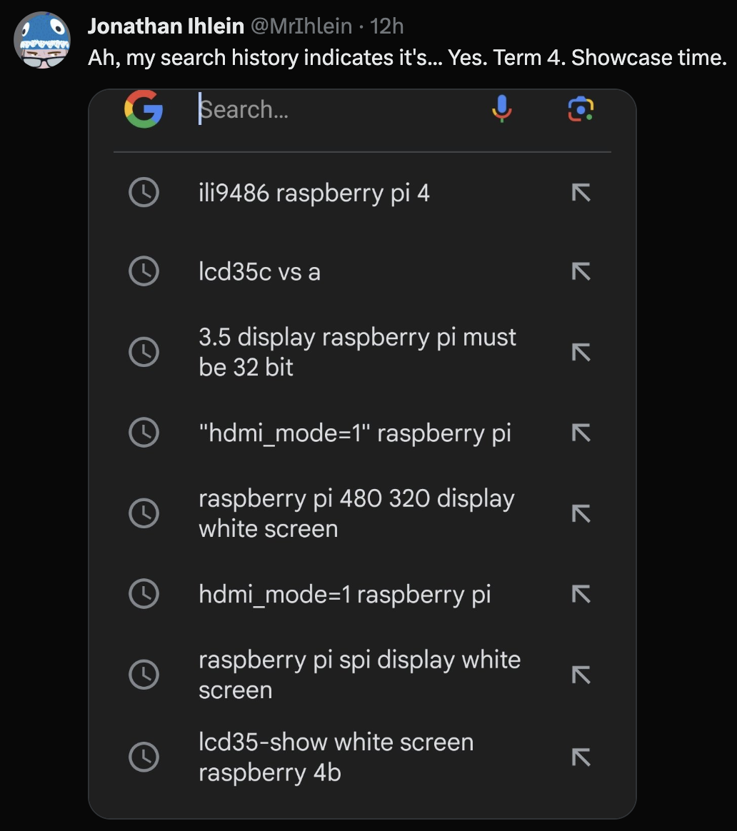
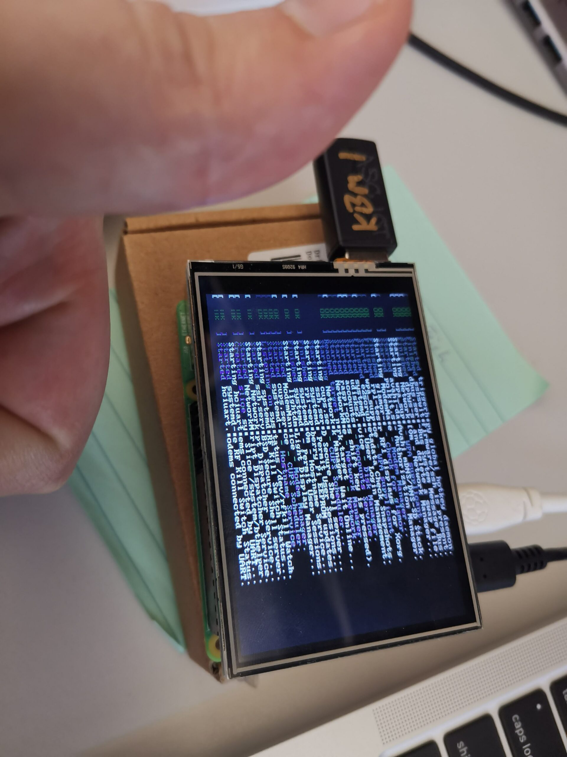
I’ve used little Raspberry Pi screen hats for various projects in the past – they are almost always a genuine pain to set up, especially if touch support needs to be calibrated, but they’re generally not more than a 30 minute job.
Except this year.
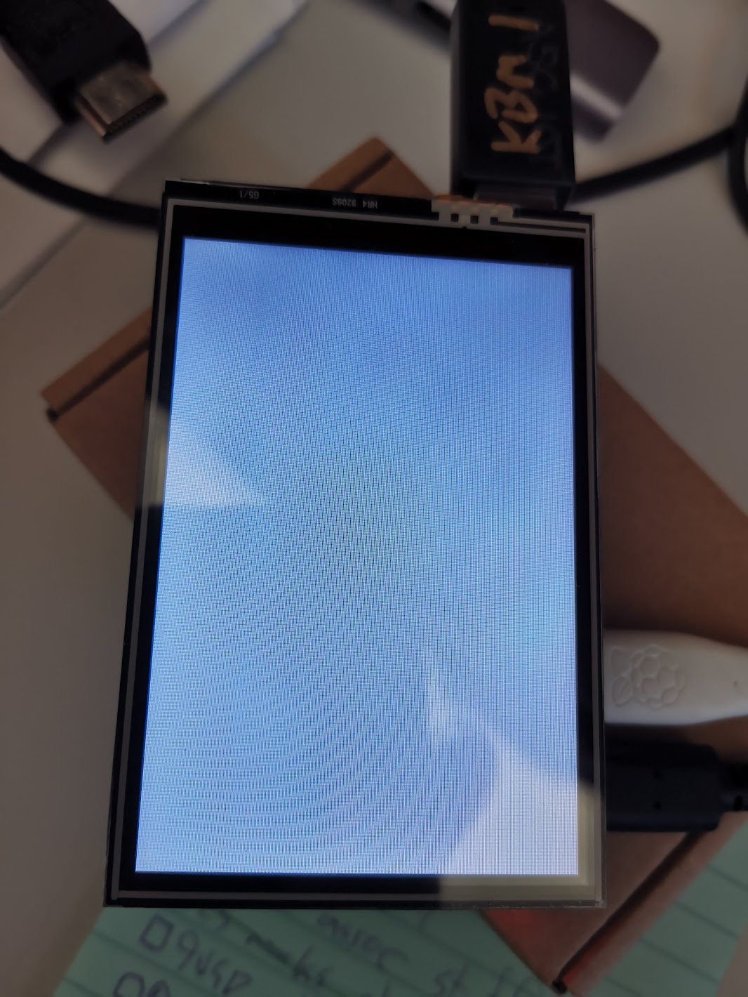
I had an old, but still on the market 3.5″ display that a student wanted to use for their project (lots of Pepper’s ghosts this year). It just would not behave with the latest Raspberry Pi OS running on a Pi 4B.
The dreaded “blank white screen”
After trying the usual suspects changes: faffing about with various almost identical drivers from Waveshare and GoodTFT (I ended up deciding that our particular hardware is the knockoff one from GoodTFT, rather than the Waveshare original), tweaking various settings in /boot/config.txt and raspi-config, I stumbled upon this post.
Long story short, the old dtoverlay setting for these displays was this:
dtoverlay=tft35a:rotate=90
But that’s apparently not supported in the new Raspberry Pi OS – you need to use this:
dtoverlay=piscreen,drm
Next challenge: to get the desktop displaying. It’ll show me a terminal login (ctrl-alt-F2), but X will not start :-/
For those of you with OCD who are twitching due to the misalinged bottom frames, this was fixed post screenshot. Sorry.
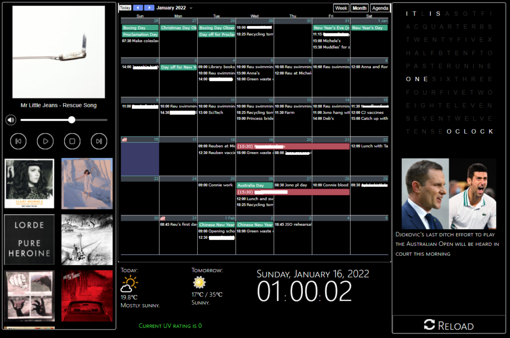
I’ve been meaning to do something like this for around a year – having an easy to view calendar not on our phones and controlling the MPD server above the kitchen were the main drivers.
I’m going to go through each component of the panel before giving an overview of how the whole thing hangs together, in an endeavour to kinda-sorta document the thing for when it inevitably breaks.
A Music Player (except not)
MPD is… quirky
I tried a few music servers before just settling on a raw MPD install. I was using a Raspberry Pi 3, but it kept freaking out with maintaining WiFi (no idea why) so I ended up with the current server – Ubuntu running on an old Mac Mini via a USB external HDD (since the SATA controller died on the Mac).
I’m astonished this thing works at all, to be honest. Even acts as a bluetooth speaker when needed.
The issue with the MPD server was in operating it – the MALP app remote controller is fine (though quirky in its own way), but not super convenient or transparent to use when wandering around the kitchen. What I wanted was an easily accessible control to simply play/stop/next and display track details.
There areexistingwebapplications I could have used for this job, but they were either too hard to configure right or hugely overkill for what I wanted. None of them quite fit right inside an iFrame either, which was frustrating.
It’s not possible to create a pure JavaScript controller for MPD – it doesn’t allow for WebSocket connections, therefore any web app solution would need a CGI backend. To whit, fine, I’ll roll my own.
What you see above is actually two iFrames – the top (player) section and the bottom (album select) section.
The top section can issue AJAX commands to the backend, written in Python using the surprisingly well-documented Python-MPD2 library.
This is all pretty straightforward, but for two things: keeping the current track data fresh and accessing album covers.
Keeping track data current doesn’t have an elegant solution – I have the JavaScript query the backend every 4 seconds and check for differences in the track name or album artwork file. It’s not fancy, but given I can’t access MPD directly via JS, keeping it constantly up-to-date is beyond my meagre ability.
MPD supposedly allows for access to binary data containing album covers, but the rules for this are opaque and inconsistent – I have a number of albums with corresponding images in the right directories, but no artwork shows up.
MALP works around this by (semi-successfully) pulling data from MusicBrainz where possible. So I did the same – an artwork backend informs the panel of the best image to use based on existing files and downloads the appropriate album cover where artwork doesn’t already exist.
This mostly works, but is hardly robust.
Album Selection
This is mostly smoke and mirrors – I lack the patience or inclination to build a system for gathering data on all the artists or albums in our collection. Instead, I figured we only have a handful of albums at any time we’re really listening to. I’ve created stored playlists for those using MALP and another backend script runs a cron job once a day to add any new playlists to the frontend.
What was most “fun” about this was of course passing the playlist names back and forth – they’re replete with lovely juicy characters such as apostrophes and ampersands which break URLs something fierce.
As a result, the JavaScript on the front end base64 encodes the playlist names before URI component encoding the base64 string and the Python backend undoes all that to load the appropriate list.
At this point I’m remembering why I never stuck with frontend development back when I worked as a dev.
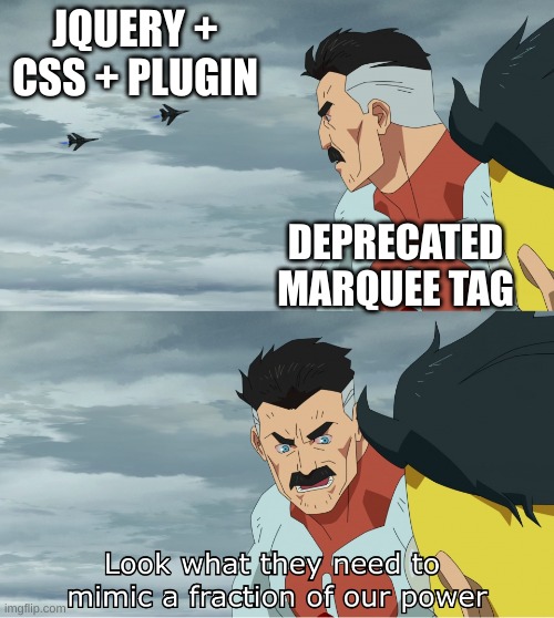
A note about JQuery:
The music player is the only part of the project to use JQuery. I resolved not to use any frameworks where possible – mostly out of bloody-mindedness, but also because it wasn’t really essential for any of the panel components – but the exception was marquee.
You see, for long track names, they won’t fit in the 300 odd pixels set aside for the player. So for those tracks, I wanted the name to scroll when the track was playing.
To get a reliable marquee effect in this day and age, you apparently have to use a JQuery plugin and about 20 lines of CSS.
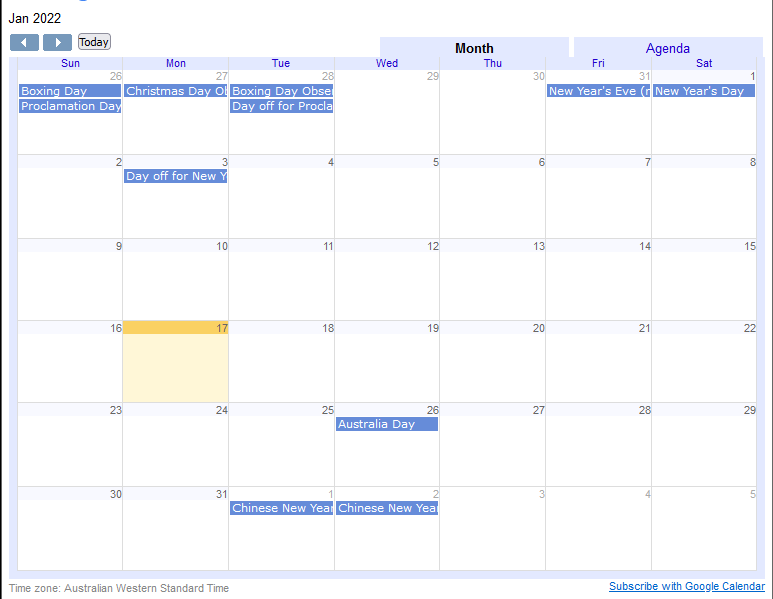
Calendar
It’s a calendar.
One does not simply make a calendar in software. Time is evil when it comes to software development – I’m torn as to whether JavaScript or the entire concept of time itself is worse.
Okay, it’s JavaScript – I have to actually use JS more often.
Rather than reinvent the extremely complex and fraught wheel of time, we can just use Google Calendar’s “embed your calendar as an iFrame” feature. Perfect!
It looks like this:
The “embed as iFrame” feature predates the popularity of dark modes in computing.
Hmm. That doesn’t look like the rest of my panel.
A brief word about the panel’s colour scheme:
I’m not good at colour schemes. More than that, I struggle to care about them much. It’s not that I’m colour blind, I’m just largely colour agnostic. I mean, I’m not going around using hotdog stand theme or something, but beyond that, well, ¯\_(ツ)_/¯
Here’s the thing though – you can’t just restyle the contents of an iFrame when it comes from someone else’s server – there are very important security reasons for that. Given this was a project purely for use in my kitchen, on a device inaccessible to the outside world, I did look for workarounds to this security policy.
As a result, I found a lot of people discussing some super bad ideas for circumventing XSS protections, and there’s probably a fortune to be made in bug bounties if I looked up their Linkedin pages and did some half-hearted prodding on the web apps run by their companies.
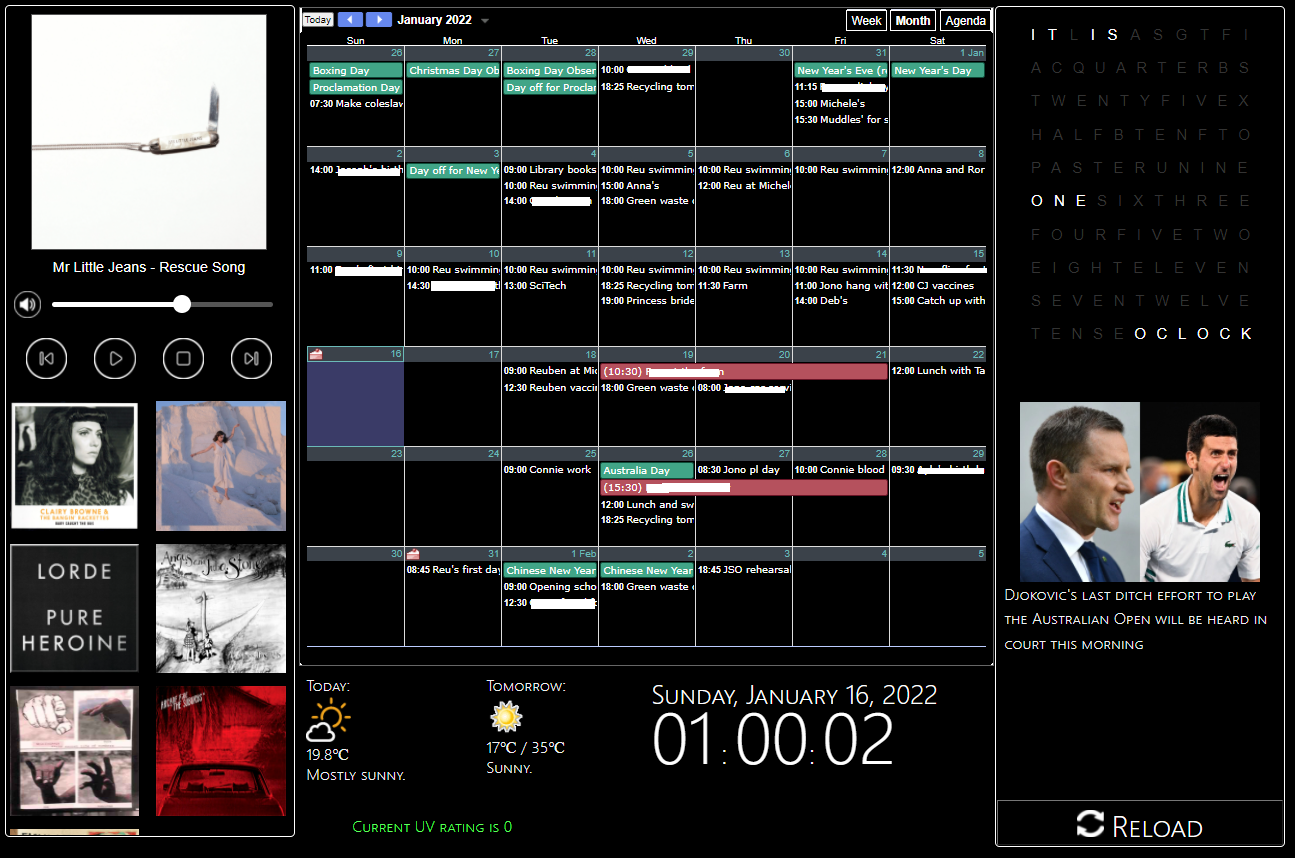
A basic userscript later and I’m forcing the browser to restyle the Google Calendar in a dark theme. It is absolutely, totally and in all other ways perfect, and I’ll not be moved on the issue.
(You’ll note the “sunny” icon in the screenshot at the top doesn’t match this one – Chrome aggressively caches images and it’s challenging to have it download a changed version)
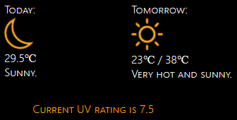
This was a hot mess. So to speak.
There exist APIs for weather which are free. None of the ones I found were worth a damn for local weather – often off by 2-6 degrees (43 degree day? It happily reports that it’s 37!)
There exist APIs which are very expensive. This is not suitable for my flimsy summer panel.
Then… there’s *coughs* scraping weather websites.
I won’t go into detail, but to ensure that the scraping only happens a handful of times a day, I wrote a Python script with Beautiful soup to snag the precis for today and tomorrow along with the temperatures and dump them into text files on the webserver. Then, the weather app reads that data in every 15 minutes or so.
Weather icons are usually pretty awful. I like these ones.
UV was… trickier.
When my wife asked for UV info, I said, “Easy. It’s summer, therefore it’s always extreme. Pack sunscreen and wear a space suit.”
But no, the spousal request was for moment-to-moment UV rating values (or thereabouts).
The official UV rating site for Australia was last updated when Kings of Leon were a big deal on the radio.
I guess at least Kings of Leon released new material since then?
Some digging unearthed a JSON file shuttling from a server to a script on the page and then into some terrible graphing libraries. As well as many, many commented lines of code that were clearly not meant to make it into production.
I pointed some more Python at the JSON file and… oh great, it’s a giant array of UV data for every minute of the day. I’m going to have to iterate through the whole thing and… wait, there’s a property at the bottom of the file called “current_uv_rating”, perfect!
Nope. It’s always set to zero.
Iterating it is. Another cron job runs the Python every half hour.
They do offer RSS feeds (am I hearing decades old music again?) which they seem to have been very enthusiastic about around the time that everyone was done using RSS feeds. Most of the info on ABC’s site regarding RSS feeds is from circa 2011, and I’m cautiously using the word “most” as that implies there’s a lot more information than there actually is. Which is close to none.
There does exist a “just in” feed – an XML file with headlines, links and relevant images for the most recent stories, regardless of topic or popularity. I don’t know what dark science or eldritch divination led me to find it, because you sure as heck can’t track it down using either Google or the ABC’s own search functionality.
At any rate, another Python script + cron job (TM) later, and I’m slurping down headlines to display every 25 seconds on the panel.
Here’s The Thing, though: when you visit an article by smearing your finger on the screen, it opens in a new tab. Which would be dandy, except the only way to get back to the panel again is to:
Press the Windows symbol on the Surface device running the panel (a feature sadly missing from more modern Surface Pros) to access the taskbar, given the panel’s browser is in full screen mode.
Access the on screen keyboard from the taskbar (no, not the pretty one. The accessibility one with all the functionality).
Press fn-F11 to drop the browser out of full screen mode.
Close the tab. Oops, you missed the little “X” with your giant finger. Try again. No, that’s a new tab. There we go.
Access the keyboard again. Press fn-F11 to go back to the full screen mode.
That dog won’t hunt, Monsignor.
War were declared.
I need a big, meaty, easily touchable “close” button on articles when they open.
iFrames are once again unsuitable for this job – I could just display the article in an iFrame with a button outside it – but ABC have (entirely reasonably) prohibited using their stuff in an iFrame, specifically to prevent nefarious purveyors of stolen bits from claiming their work as their own (not that I’m a purveyor of stolen bits. I don’t purvey them, thank you very much.).
Once again we turn to… Userscripts. Hooray.
The CMS used by our National Broadcaster is, like all CMSes, prone to creating multiple obscure classes in its HTML.
Therefore finding the right element to inject a button into was tricky.
It’s not robust by any means, but it currently finds the second link on the page (the ABC logo) and sticks a close button right next door. It then tracks down the “FixedHeader” data component in the page and injects another button – this is the overlay banner that sticks around at the top once you scroll down.
Et voila – one click return to the panel.
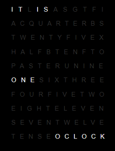
The #bestoftimes, the #worstoftimes
Fig 1: A somewhat silly clock
This is a Javascript clock. It is pretty silly. Maybe one day I’ll replace it with a graph of utilities usage or something. It’s a nice clock though.
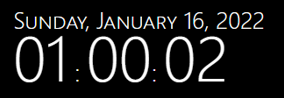
Fig 2: A less silly, but far more boring, clock
This is another clock. This one is more sensible and useful. I don’t know what it might do on Wednesdays in September since I didn’t use a fixed width font and it’s pretty close to the full width of its container.
I’ll be shocked if the panel is still fully working in September though.
How does this dang thing work?
It runs on an old Surface Pro, which is comically overpowered for the job it needs to do. That said, it is quite old and water damaged – part of the reason for the dark theme (apart from the fact that everyone’s doing it, it’s cool man, what are you, some kind of square?) is because water ingress damaged the screen some time ago, leaving weird blotches that are only visible when displaying bright images.
The panel itself is just some HTML with iFrames and a little JS to reload the calendar and weather. It’s actually not even hosted on the Surface, but instead sits on our media centre PC/NAS.
The media centre runs the necessary backend cron jobs and hosts the music, which is played on the third, far more interesting and terrifying PC, the MPD server.
To sum up – this runs off three physical machines, 3 cron jobs, a locally hosted site, an MPD server, two userscripts which are dependant on their target sites “not changing too much”, various Python scripts for scraping sites (which also need to not change much, please and thank you) and a Python script parsing and processing an RSS feed that its owner no longer seems to care for.
The panel’s days are numbered – everything on the web is transient, even local pages which are only used in a single household.
This isn’t necessarily a bad thing – a bit over a year ago, we had a Google Nest we’d received for “free”. It was fine.
It played music – but not necessarily the music we wanted or in the order we wanted. And it had ads.
It could tell you the weather, but you had to ask.
It could tell you your schedule, sort of.
It could add to our shopping list – provided you used the shopping list page Google created, which has no API.
When it stopped working, I searched for a solution and found nothing useful. It was apparently a known flaw. Had we paid for it, we’d probably have some recourse for replacing it.
I didn’t feel the need to buy another.
At least when this panel breaks, I’ll be able to find out why and have a chance at fixing it.
So I’ve been getting emails from Let’sEncrypt telling me that my certs are coming in through the old ACME v1 protocol and that if I wish to continue receiving certificates, I need to update my certbot.
I figured this was just because the Ubuntu version I had been running was a little on the old side and was no longer receiving non-security updates, prompting me to update to Bionic (v18).
But the emails kept coming, and it became apparent that the version of certbot I had was woefully out of date (0.31 vs 1.3.0).
And yet… the EFF’s website containing guidance for getting certbot up and running on various systems still provides a guide for installing using the PPA. There is a justification for doing so, but as of June 2020, the software installed via PPA will be useless, so I’m not entirely sure why it’s still the recommended method 2 months out.
At any rate, here’s what I did to update mine in order to continue working with my hosting software:
That ain’t all though. This worked fine on my main server, but the secondary server threw an error:
/usr/local/bin/certbot-auto --help
Requesting to rerun /usr/local/bin/certbot-auto with root privileges...
Creating virtual environment...
Traceback (most recent call last):
  File "<stdin>", line 27, in <module>
  File "<stdin>", line 19, in create_venv
  File "/usr/lib/python2.7/subprocess.py", line 185, in check_call
    retcode = call(*popenargs, **kwargs)
  File "/usr/lib/python2.7/subprocess.py", line 172, in call
    return Popen(*popenargs, **kwargs).wait()
  File "/usr/lib/python2.7/subprocess.py", line 394, in __init__
    errread, errwrite)
  File "/usr/lib/python2.7/subprocess.py", line 1047, in _execute_child
    raise child_exception
OSError: [Errno 2] No such file or directory
Turns out, that “no such file or directory” came from the fact I’d never used virtual environments on the secondary server.
Running certbot with the –version arg should then show you a current version.
I’m surprised at how little support the deb based systems are getting from the certbot crew – I’ve been otherwise impressed with Let’sEncrypt’s work thus far.