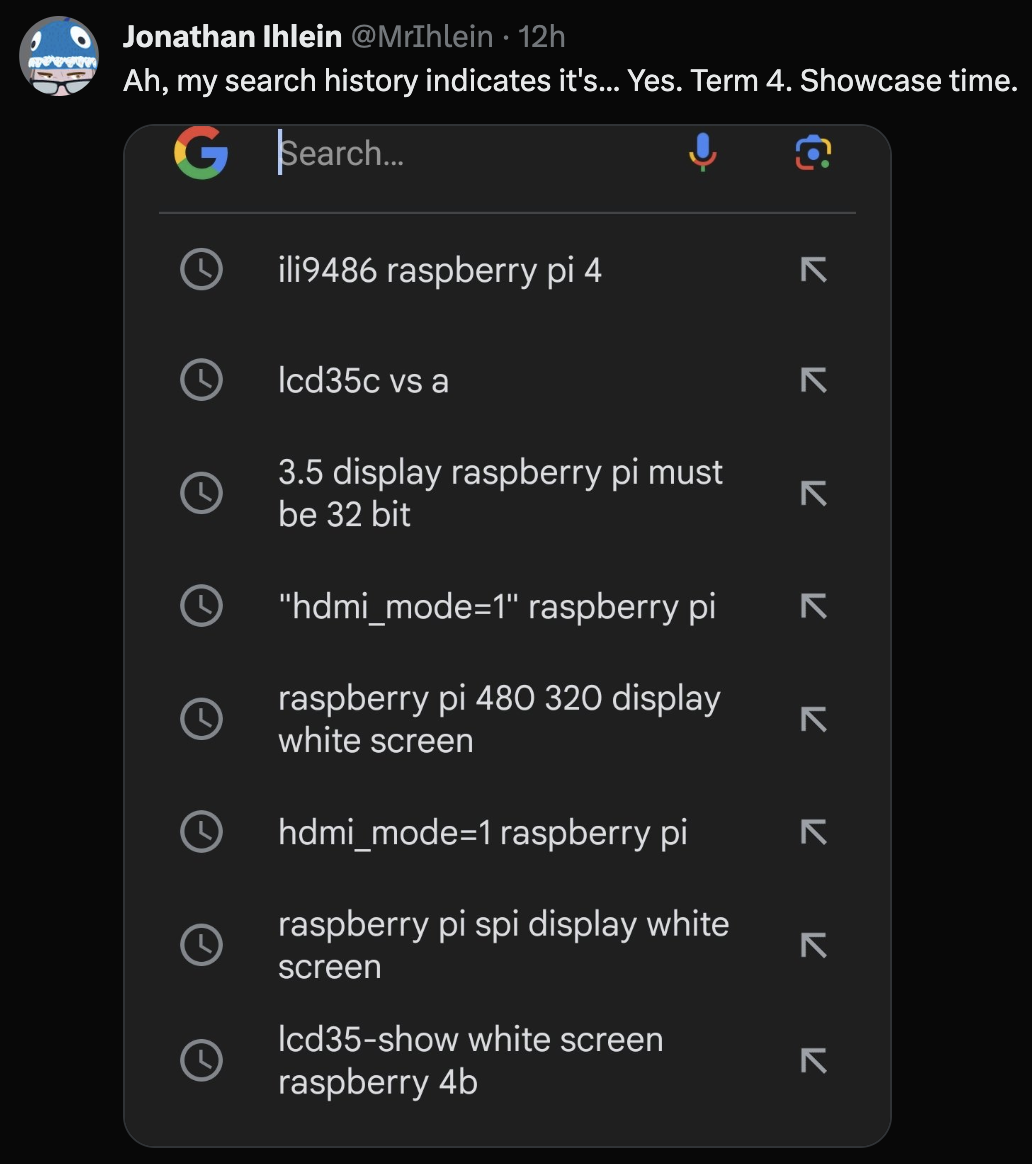
I’ve used little Raspberry Pi screen hats for various projects in the past – they are almost always a genuine pain to set up, especially if touch support needs to be calibrated, but they’re generally not more than a 30 minute job.
Except this year.
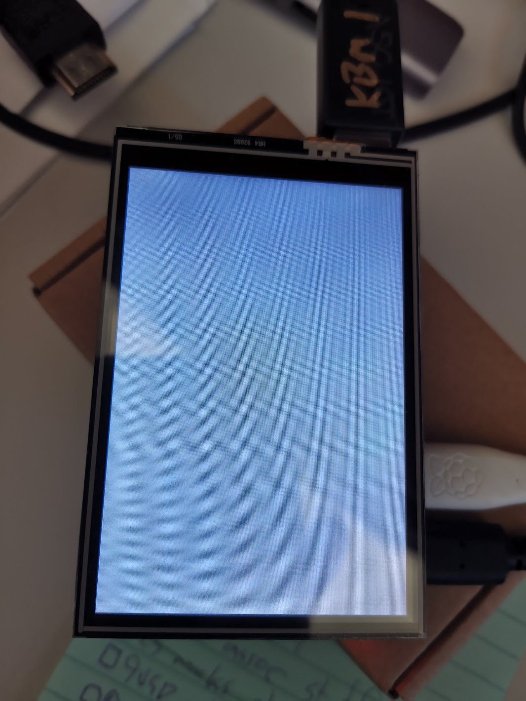
I had an old, but still on the market 3.5″ display that a student wanted to use for their project (lots of Pepper’s ghosts this year). It just would not behave with the latest Raspberry Pi OS running on a Pi 4B.
The dreaded “blank white screen”
After trying the usual suspects changes: faffing about with various almost identical drivers from Waveshare and GoodTFT (I ended up deciding that our particular hardware is the knockoff one from GoodTFT, rather than the Waveshare original), tweaking various settings in /boot/config.txt and raspi-config, I stumbled upon this post.
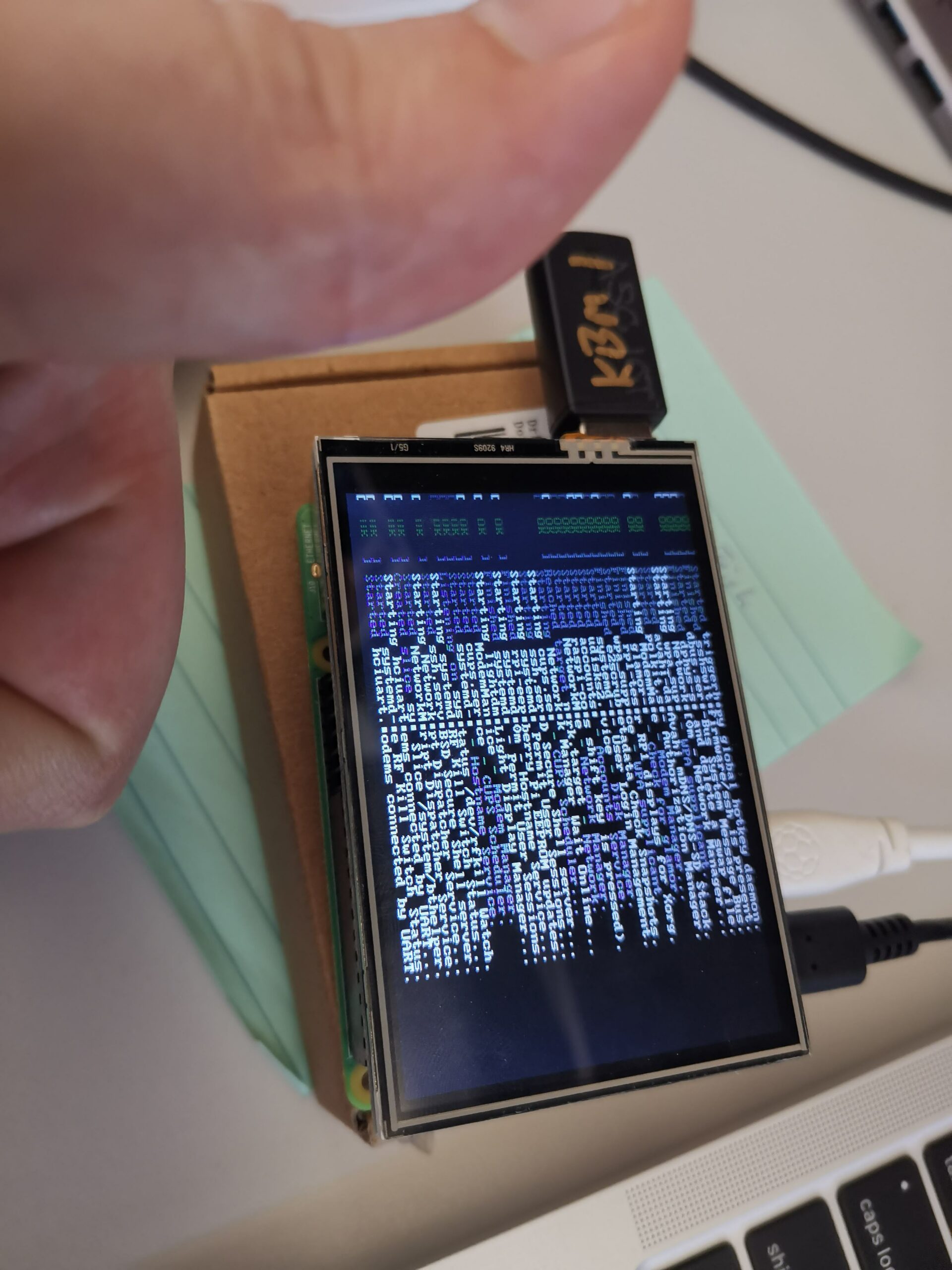
Long story short, the old dtoverlay setting for these displays was this:
dtoverlay=tft35a:rotate=90
But that’s apparently not supported in the new Raspberry Pi OS – you need to use this:
dtoverlay=piscreen,drm
Next challenge: to get the desktop displaying. It’ll show me a terminal login (ctrl-alt-F2), but X will not start :-/
I haven’t worked often with Arduinos or similar devices (Micro:bits notwithstanding) and the primary reasons are twofold:
Residual trauma from having written code in C++ years ago
Working in meatspace is inherently icky to me, as someone who has only dabbled comfortably with software in the past.
Software is often ineffable – particularly when you’re writing in unfamiliar languages and especially when you’re writing code where you have a slippery grasp on the mechanics1. This is exacerbated when the error could be in your software, how you transferred it to the device, in the wiring of the peripherals or in the peripherals themselves.
However, for certain projects, the need to work with physical components cannot be circumvented – and thus, the small necessity of creating an ultra simple USB keyboard, which is actually just a button connected to an Arduino.
We have Arduino UNO R3s coming out the walls here – they seem to have come with various kits over the years and so they’re in plentiful supply. Fortunately, this guy did it already – seven years ago, no less – and it seems straightforward enough.
I will stress that I am a newcomer to the world of Arduino, so I may have the following things wrong, but as I understand it, the process works like this:
The UNO has a processing chip that does the execution of a program. It can be programmed to, amongst other things, detect a button push and send a character code (or bunch of ’em) through the USB chip.
The USB chip exists to provide a serial interface for transferring code to the UNO. Not for being a HID2. But – and props to Arduino for making this so easy – the firmware that runs that USB chip can be replaced, such that it behaves as a USB HID and not for transferring programs.
A Button for Vs
Largely arbitrarily, my connected program requires the user to press “V” in order to trigger a reset. There is no keyboard connected (and I don’t want there to be one). My UNO single button keyboard to the rescue.
Step one is to write the code and transfer it to the UNO. Mine is a little different to other examples I’ve seen:
//A Button for Vs - using external pullup resistor
int ledPin = 8; // My LED is connected to the pin labelled "8"
int state = 0;     // Initialising the state to "not pushed"


uint8_t buf[8] = { 0 }; //A buffer array for our chars

#define PIN_BUTTON 2 //Button is connected to pin 2

void setup()
{
  Serial.begin(115200); //The version of the USB firmware supports a baud of 115200
  pinMode(ledPin, OUTPUT);  // declare LED as output
  pinMode(PIN_BUTTON, INPUT);    // declare pushbutton as input

  delay(200);
}

void loop()
{
  state = digitalRead(PIN_BUTTON);
  if (state == HIGH)
  {         // check if the input is HIGH (button released)
    digitalWrite(ledPin, LOW);  // turn LED OFF
  }
  else
  {
    digitalWrite(ledPin, HIGH);  // turn LED ON
    buf[2] = 25;    // Letter V
    Serial.write(buf, 8); // Send keypress
    releaseKey();
  }
}

void releaseKey()
{
  buf[0] = 0;
  buf[2] = 0;
  Serial.write(buf, 8); // Release key
  delay(500); //This prevents a bunch of presses registering
}
First, there’s the presence of the LED – feel free to omit this. I added it when things weren’t going so well (read on) to provide some indication that the software was actually running.
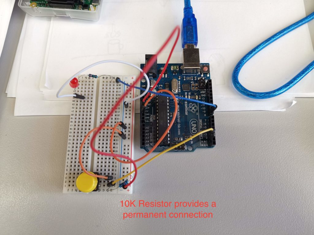
Second, I’ve explicitly mentioned the use of an “external pullup resistor”. I note this, because, as a noobie to the field, I had no idea what the heck this was or even if I needed it. The reference code and circuit diagram ignored it completely (and worked, briefly). Some sites explicitly insist on a resistor being wired in (see below) and others talk about mysterious “internal pullups” and have slightly different code and diagrams without the resistor.
So what gives?
Reasonable explanations abound, if you go looking. In short: it’s not enough to just have a button/switch wired in that can be opened or closed, because meatspace sucks the wibbly wobbly nature of the real world means that all sorts of little voltages can register in that open circuit. This is called a “floating” state, and since it’s undefined, we need to nail it down, and we do that by creating a second part to the button circuit that is permanently connected (and thus permanently either HIGH or LOW, depending on how you connected things). When the button is pressed, it creates a new connection in that circuit, which results in the opposite state. All very predictable and much safer.
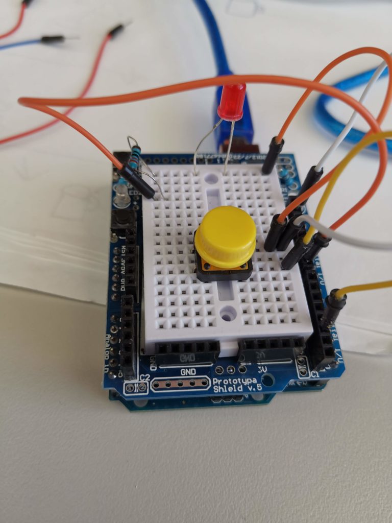
My setup using an external pullup is here:
UNO HID, with a button using an external pullup resistor
But there’s a better way to go – the UNO does, in fact, have internal pullups. You can use these instead, by making small changes to the code, and results in cleaner wiring and fewer components.
The difference is not super obvious, but it happens where you declare the pin mode for your buttons: pinMode(PIN_BUTTON, INPUT_PULLUP);3
UNO HID configured to use internal pullups. I’ve moved to a tiny breadboard mounted on a prototyping shield, but it’s the same otherwise.
Why did I faff about with resistors so much?
Because I did some silly things first.
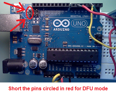
Flashing Firmware – Even when it’s safe, it’s dangerous
Flashing the firmware on the UNO is surprisingly pain-free. You use a screwdriver to short the reset pins on the UNO, you get a program called “dfu-programmer” and point it at the appropriate firmware file and it’s done. More or less.
It was the “more or less” that got me.
You see, the process is a little more involved than that. First, you upload a program like the one above. Then you need to erase the existing firmware to make room for the new one. Then you upload the new one. Then you reset it using dfu-programmer.
That’s three commands which are easy to mix up when you’re in a hurry.
They have to be done in the right order. And if you want to change the program that’s running on your new “keyboard” (for example, to alter the key or add new buttons, or add a longer delay) – you first have to flash it back to the original firmware to let it upload the program, then flash it again to the keyboard firmware to test it.
To make my life “easier”, I wrote two scripts to issue these commands. And because I am super clever, I chained the commands with the logical “and” – && – to ensure that the proceeding commands would only run if the previous command were successful.
My Mac took this to mean “run the commands in any order”4. I spent an hour or so trying to get my formerly working keyboard to do anything, before realising that it was flashing the firmware and then cheerfully erasing the firmware it had just flashed.
Sigh.
The moral here is to run the commands manually, or at the very least read the output which will tell you exactly what it is doing.
Addendum: HID numeric codes for keyboard presses can be found here.
The first indicates that it will sync with MacOS and work with Android. I could only get a brief sync with MacOS sometimes and while it synced with Android, I couldn’t get any keystrokes to show up.
The second briefly showed up as a possible pairing device, but beyond that I got no joy. It doesn’t help that I couldn’t understand just about any of the code.
Revising Expectations
Okay, this is beyond my abilities at the moment. But there’s a cheaty way – based on the concepts used in this project.
Sam El-Husseini’s project uses three easy to implement components:
Pushing data to the serial bus (USB) from the Micro:bit when a button is pressed
A listener program on the host device that turns the data from serial into actions on the host
A second/more Micro:bits that send Bluetooth messages to the first device – in this way, it would act as a proxy (basically a proprietary dongle).
Component 3 is compelling, because implementing Bluetooth communication between Micro:bits is almost comically easy in the interpreted languages (such as Python, Javascript etc). I imagine its probably significantly easier to implement in C++ than proper BT pairing too, but I’ll cross that bridge when I’m good and ready.
Part 1 – Proof-of-Concept Tethered Device
I decided to implement the first two components and leave the third for another time 6.
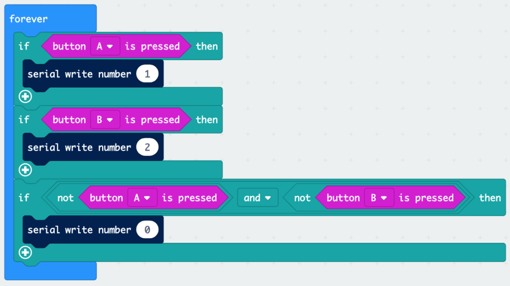
The tethered MB uses very similar code to Sam’s project above:
Javascript is spawned from the third circle of hell, but I’ll be damned if it isn’t easy to use in this case
basic.forever(function () {
    if (input.buttonIsPressed(Button.A)) {
        serial.writeNumber(1)
    }
    if (input.buttonIsPressed(Button.B)) {
        serial.writeNumber(2)
    }
    if (!(input.buttonIsPressed(Button.A)) && !(input.buttonIsPressed(Button.B))) {
        serial.writeNumber(0)
    }
})
The only modification here is to send a stream of numbers rather than linefeed delimited strings7.
The third if statement is to work with the key events that the host program needs to implement – if we’re just typing, sending the keystrokes in isolation is fine, but we need to indicate when a key is pressed and when it should be released. The 1s and 2s indicate when A and B are pressed respectively. The 0s indicate that nothing is being pressed. Is it bad and naughty that I’m sending a constant stream of zeros when nothing is happening? I’ll fix it in the first beta/third production patch.
I’ve never used Node before, so I had a go at using Node as per Sam’s project. It works great for his purposes because there’s a specific Node module for integration with Spotify. I needed something more general-purpose. The only two modules I could find were a keyboard simulator that is a wrapper for a JAR file and requires full-blown Java VM and robot JS which is also pretty big for my needs, but hey, let’s give the robot a go.
The issue with robot is that it implements a function called “keyTap”, which, well, taps a key. If you’ve ever watched someone use a controller, they ain’t sittin’ there tapping the buttons, they’re pressing and holding most of the time.
No dice. Back to Python.
Part 2 – Host Program
import serial
from pynput.keyboard import Key, Controller
ser = serial.Serial('/dev/tty.usbmodem14202', 115200)

keyboard = Controller()

last = 0

while 1:
  serial_line = int(ser.read())
  if serial_line != 0:
    last = 1
    if serial_line == 1:
      keyboard.press('a')
    elif serial_line == 2:
      keyboard.press('d')
  elif last != 0:
    keyboard.release('a')
    keyboard.release('d')
    last = 0
Python provides two modules for our purposes: serial and pynput.
Pynput gives us much finer control over keyboard simulation – pressing and holding and releasing keys, among other functions.
There’s really not a lot to the host program – it’s surprisingly simple. The one point to note is the use of the “last” variable.
During testing, I noticed that the host program was blocking normal keyboard input – this is because the constant stream of 0s was causing it to continuously trigger key releases for the related keys, rendering the keyboard useless for those keys. The use of a test for whether or not the release command has been sent removes that unintended side effect. I investigated putting similar code into the Micro:bit program, but the nature of the byte stream meant that the 0s didn’t always register with the host program.
Any necessary improvements are indicated in the todo list below.
Proof of concept using a silly pygame Spider-man thing I made
Wait – what’s the point?
“But Jonathan,” you say, “What’s the point of a controller with only two buttons? Even Tetris requires at least four!”
Ah, you’re forgetting about… Tron:
14 years and still going strong…
Armagetron Advanced, to be exact. Played with just two buttons (unless you’re a coward who uses the brakes).
In all seriousness, the proof of concept is for a more ambitious project: Micro:bits can be easily connected to a breakout board which allows for a wide array of inputs, buttons etc to be connected to its IO pins.
In theory (and what I’d like to do with my video game design class) one could design the composition and layout of their own “ideal” controller and create a Micro:bit program to pipe commands to serial.
Laser cutting or 3D printing the necessary structure of the controller should be straightforward enough (we’re not shooting for aesthetic design awards). The end result is a custom controller powered by any Micro:bit.
Now that this proof of concept is complete, there’s a little more work to be done.
Todo List
Test with compiled, rather than translated code on both the host and Micro:bit. It could have been my imagination, but it felt that the controller was a touch delayed, which would make sense given the pipeline from physical button to simulated keypress.
Test with two Micro:bits – using the tethered MB as a dongle for the “wireless” one.
Connect external physical buttons and joysticks to the MB IO pins. This process is well documented and I do not anticipate it to be particularly difficult8
Investigate removing or mitigating the zero stream when the device is idle.
Investigate using Bluetooth to connect as a direct serial device without pairing – no idea if possible or easy, but would allow a similar serial streaming process with the need for a dongle MB.
Modify the host program to autodetect the appropriate port.
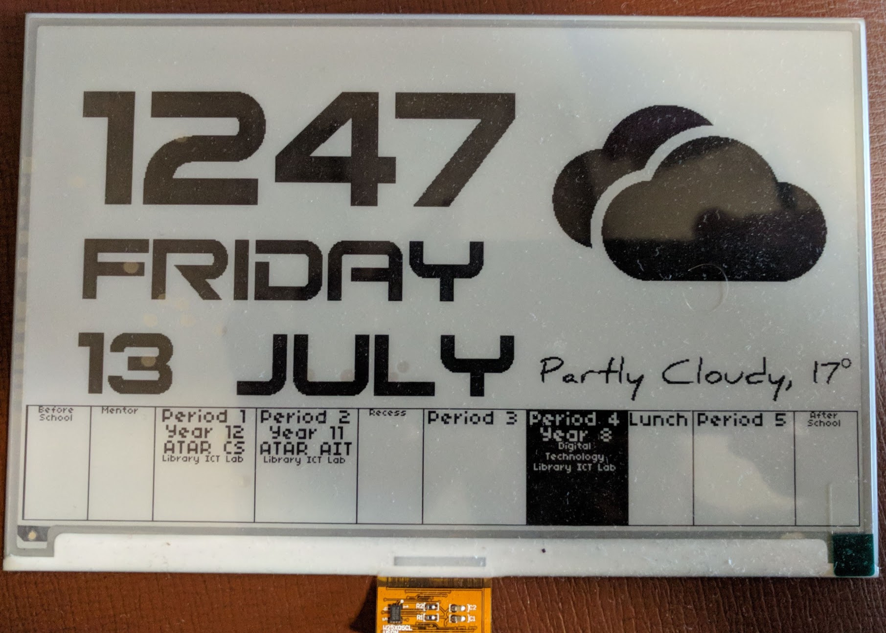
The panel is great for its price and ease of use – Waveshare ship this model with a Raspberry Pi hat and provide a number of software libraries for interacting with them.
I’ll follow this up with a breakdown on how I created my wall clock, but just quickly, a quibble with Raspberry Pi/headless systems in general:
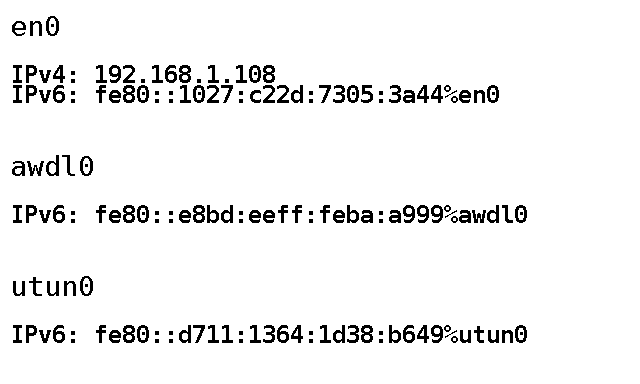
My place of work has a… restrictive network when it comes to BYOD. It’s better than it used to be, but unless you can easily connect to an enterprise wifi network (difficult, but not impossible with the Pi) you’ll need to connect an ethernet cable (and not mention it to the techs). In either case, you’ll get an IP address. But you won’t be able to figure out what IP address without plugging in a display.
There is an opportunity with a display like this to work around this problem: run a program on start up to push the IP addresses of all network interfaces to the panel.
Without further ado, PaintIP, a small Python script that will get a list of IPs for your interfaces and paint them to the panel:
PaintIP running on a Mac, which seems kinda pointless
The “screenshot” pictured here is actually the image generated by the program which is then pushed to the panel.
It’s a minor thing, but sometimes the ability to bring your device in from home, plug it in and immediately know which IP to SSH to is a lifesaver.
Rejected (and hilarious) alternative:
A program which simply takes a screenshot of the primary console, munges it into the right resolution at 1 bit colour and paints the display every 6 seconds (why 6 seconds? because this particular panel has a 6 second refresh – not ideal, but mostly workable).
I actually made this abomination, based on a technique from this here blog post.
It literally just uses snapscreenshot and ImageMagick’s convert program to create the 1 bit image of appropriate resolution and then calls a Python script to display said image.
Could I have put all this in a single Python script? Probably, but it’d have system calls to run snapscreenshot and convert (Python’s ImageMagick libraries leave much to be desired) and honestly I just needed the thing working now.
Curator is a very basic script that takes an image as an argument and displays it on the E-Paper panel – barely a modification of Waveshare’s example script.
Still, there might be the odd time when it’ll be useful to see a shot of the console for debug purposes – nothing stopping someone from configuring a hardware button to run the console dump shellscript.
Oh, and there are a handful of ways to get a program running on startup with a Pi, but the one I ended up using is simply inserting it into rc.local.
I never learned to code with Python; my first forays into development were with batch files (I kid you not) and then Visual Basic (which taught me many things I spent years unlearning).
Python is, in many respects, a great language for learners (which I’m not going to discuss today).
There is however, a great deal of… less than intuitive show-off code that can be, nay is encouraged to be, written using the language. Solutions are deemed to be “Pythonic”, a term as nebulous as “elegant” and often resulting in code just as unreadable to the casual observer or Python learner.
In some respects, this is about reducing the number of lines written – something fraught with peril for someone new to coding.
But there is a seductive element to Pythonic solutions – they don’t require you to twist yourself up in lines of boilerplate just to overcome a (often commonly encountered) problem.
The “with” keyword is not especially unique to Python, but is actively encouraged, and with good reason. This is one case where fewer lines is definitely better. Continue Reading…
I’ve never had cause to use executemany before, so perhaps it is unfortunate that my first encounter be in the context of oursql’s somewhat anaemic documentation.
I’ve just spent well over an hour trying to get a simple executemany statement to work – in retrospect, the solution was obvious. But the presence of an example (just one!) would have made things immediately clear.
To that end:
reportDB = oursql.connect(host = "localhost",
                          user = "LapsedPacifist",
                          passwd = "ContentsMayDiffer",
                          db = "AnythingLegalConsidered")

with reportDB as query:
  query.execute("BEGIN")
  query.execute("""
                INSERT INTO assets(clientid, assettype, model, deployed, name)
                VALUES(?, ?, ?, ?, ?)
                """, (clientID, ASSET_TYPE_UNKNOWN, model, deployed, name))

  assetID = query.lastrowid
  addresses = []

  for ip in ips:
    addresses.append([assetID, ip])

  query.executemany("""
                    INSERT INTO asset_ips(assetid, ipv4address)
                    VALUES (?, ?)
                    """, (addresses))
That’s it – just as oursql’s parameterisation is looking for a list of parameters, executemany is looking for a list of parameter lists – not just a list of strings.
Hence the for loop creating a list with the two parameters and then appending it to the executemany parameter list.
I’m sure there’s a better, more pythonic way of doing that – please let me know if I’m missing something obvious.
And behold, the grand total of what oursql’s documentation has to say about executemany:
Additionally, executemany() is lazy; if passed a generator or any other iterator which does produces values lazily, values will only be taken from the iterator immediately before they are sent to the database.
executemany(query, parambatch)
Execute the same query with different sets of parameters. This is more efficient than calling execute many times with the same query.
I don’t want it to sound like I’m down on oursql – I feel it’s the superior library for MySQL in Python, and it’s still quite young – but this particular gap in the documentation had me pulling out my hair.
I’ve read some complaints regardingscalability of executemany in oursql – fortunately my code won’t ever have to handle huge numbers of queries at one time.